What You Need to Know Before Starting a 3 Phase Meter Installation
A proper 3 phase meter installation is one of the most critical steps in bringing high-capacity power to a commercial or industrial facility — and getting it wrong can mean inaccurate billing, equipment damage, or serious safety hazards.
Here is a quick overview of what the process involves:
- Determine your supply type — Confirm whether your site needs a 3-phase service (typically 208V or 480V) versus a standard single-phase supply.
- Choose your metering method — Select direct-connect metering for lower-amperage loads, or CT (current transformer) based metering for high-amperage services.
- Plan your wiring configuration — Identify whether your system uses a 4-wire wye or 3-wire delta setup before touching any terminals.
- Meet permit and code requirements — Pull the required permits from your local Ohio building department and coordinate with your utility provider.
- Install and commission — Wire meter terminals in sequence, verify phase rotation, check CT polarity, and document all readings before energizing.
Three-phase power is the standard for facilities running heavy machinery, large HVAC systems, or high-density electrical loads. Unlike a typical home’s single-phase 120/240V supply, a 3-phase system delivers power across three alternating currents — providing smoother, more efficient energy flow at higher capacity. Commercial demand continues to grow alongside EV charging infrastructure, manufacturing, and data center expansion.
Getting the installation right from the start matters. Roughly 68% of failed panel meter installations trace back to one mistake: confusing 3-wire delta wiring with 4-wire wye on the meter terminals. That single error can cause phantom voltage readings, inaccurate kWh logging, and costly service calls.
I’m Aaron, owner of Buckeye Electrical Solutions LLC, and I’ve overseen dozens of permitted electrical projects across Northeast Ohio — including complex commercial rewires and service upgrades where 3 phase meter installation was a core part of the scope. In this guide, I’ll walk you through every step so you understand exactly what a compliant, safe installation looks like.
Common 3 phase meter installation vocab:
Understanding 3-Phase Power vs. Single-Phase Systems
To understand why a 3 phase meter installation requires specialized planning, we must first look at how three-phase electricity differs from the single-phase systems found in standard residential properties.
Voltage Levels and Power Delivery
A typical home uses a single-phase, split-phase system. This configuration delivers 120V for standard outlets and 240V for heavy appliances like dryers or ranges. While this is perfect for domestic needs, it operates on a pulsating wave cycle.
In contrast, a three-phase system delivers three separate alternating currents, each offset by 120 electrical degrees. Because these phases peak at different times, the power delivery never drops to zero. This continuous, non-pulsing flow is highly efficient for driving large electric motors and heavy industrial equipment without causing excessive wear.
In commercial and industrial settings across Ohio, three-phase power typically operates at:
- 120/208V Wye: Common in offices, retail spaces, and schools to run standard 120V office equipment alongside 208V motors or HVAC systems.
- 277/480V Wye: The standard for manufacturing plants, warehouse lighting, and heavy machinery.
- 240V High-Leg Delta: A specialized legacy configuration that provides both 240V three-phase and a 120V single-phase tap, often used in older commercial workshops.
Delta vs. Wye Configurations
The wiring configuration of your service determines how your meter must be connected.
- Delta Systems (3-Wire): These consist of three hot phase conductors without a neutral line. Delta configurations are primarily used for heavy industrial motor loads where neutral connections are unnecessary.
- Wye Systems (4-Wire): These consist of three hot phase conductors and a shared neutral wire. Wye systems are highly versatile because they can supply both single-phase and three-phase loads from the same panel.
Confusing these two configurations during a panel setup is a leading cause of installation failures. If you are planning a system upgrade, understanding your facility’s power demands will help you decide whether a standard service or a higher-capacity upgrade is required. You can read more about panel sizing in our guide on whether your facility is ready for a 400 Amp electrical panel upgrade.
Planning Your 3 Phase Meter Installation
A successful 3 phase meter installation requires careful matching of equipment to your operational load. Before purchasing hardware, we must determine the appropriate metering method and verify compliance with local Ohio utility standards.
Direct-Connect vs. CT-Based Metering
How your meter measures current depends entirely on the size of your electrical service:
- Direct-Connect Meters: These are wired directly in-line with the main service conductors. All current flowing into the building passes through the meter itself. Direct-connect meters are typically limited to services under 200 Amps.
- CT-Based (Current Transformer) Metering: For services exceeding 200 Amps, routing thick industrial cables directly through a meter is impractical and dangerous. Instead, we use Current Transformers (CTs). These donut-shaped sensors fit around the main phase conductors, stepping down the high primary current to a safe, low-voltage secondary current (typically 0-5A or 0-0.333V) that the meter can safely read.
Wire Sizing and Clearance Specifications
According to the National Electrical Code (NEC), conductor sizing must match the ampacity of your service. For a standard commercial 100 Amp three-phase service, we typically install #4 Copper or #2 Aluminum conductors. However, larger commercial applications require precise calculations to limit voltage drop, especially over long runs.
Physical clearance around the meter socket is also strictly regulated to ensure safety during inspections and maintenance. Ohio utilities require:
- Height: The center of the meter dial must typically be mounted between 4 feet and 5.5 feet above the finished grade.
- Working Space: A minimum of 3 feet (36 inches) of clear, unobstructed workspace must be maintained in front of the meter enclosure.
- Separation: The meter box must be kept at least 3 to 5 feet away from gas meters, regulators, or other potential ignition hazards.
Ohio Utility Standards
Every major utility provider in Ohio maintains its own specific compliance manual. If you are installing a meter in Northeast Ohio, you must consult the appropriate guidelines:
- For customers in central and southern Ohio, review the [PDF] Guide for Electric Service and Meter Installations – AEP Ohio .
- For Northern Ohio areas served by FirstEnergy companies, consult the [PDF] Customer Guide for Electric Service – Ohio December 2023 .
- For Western Ohio, reference the [PDF] Electric service handbook – AES Ohio .
Step-by-Step 3-Phase Meter Wiring and Setup

Wiring a three-phase meter requires strict adherence to safety protocols and precise execution of connection sequences. Below, we break down the process from pre-installation planning to physical wiring.
Preparing for a 3 Phase Meter Installation under NEC and Ohio Codes
In Ohio, all electrical installations must comply with the state-adopted version of the National Electrical Code. Ohio’s 2023 NEC adoption includes expanded GFCI requirements in several locations, qualifying specific rules (such as those for commercial kitchens or outdoor service equipment) as situational rather than universal.
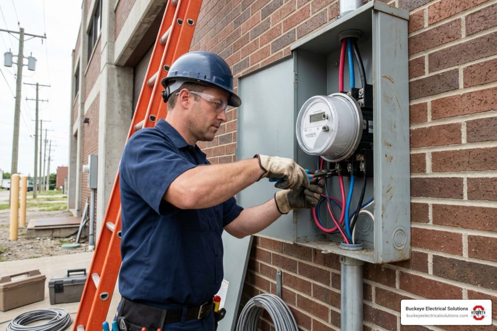
Before starting any physical work, we must secure the necessary permits from the local building department (such as the City of Cleveland or Summit County). Working on live commercial services is highly dangerous and requires strict compliance with NFPA 70E safety standards, including appropriate personal protective equipment (PPE), insulated tools, and a verified lockout/tagout (LOTO) protocol. For a detailed look at what local inspectors look for, see our guide on electric meter inspections.
Wiring Configurations for Wye and Delta Systems
Once the service is safely de-energized, we can begin mounting and wiring the meter.
1. Wiring a 4-Wire Wye System (e.g., 120/208V or 277/480V)
In a 4-wire Wye system, the meter requires connections for all three phases (Phase A, B, and C) plus the neutral conductor.
- Step 1: Mount the meter enclosure securely using corrosion-resistant hardware.
- Step 2: Route the incoming line-side conductors from the utility. Connect Phase A to terminal 1, Phase B to terminal 3, Phase C to terminal 5, and the incoming neutral to terminal 7.
- Step 3: Connect the outgoing load-side conductors to the main distribution panel. Connect Phase A to terminal 2, Phase B to terminal 4, Phase C to terminal 6, and the load neutral to terminal 8.
- Step 4: Ensure all terminal screws are torqued precisely to the manufacturer’s specified inch-pounds using a calibrated torque wrench.
2. Wiring a 3-Wire Delta System (No Neutral)
For Delta installations, we utilize a 3-wire metering configuration. Because there is no neutral conductor, the meter uses the two-wattmeter method to calculate total energy consumption.
- Step 1: Connect Phase A and Phase C through their respective terminals.
- Step 2: Phase B is typically used as the reference phase and is connected directly to the meter’s reference terminal.
- Step 3: If using a multi-system meter like the PowerHawk 6103, 6203 and 6303 meters , ensure you select the 3-wire Delta mode in the meter’s programming menu before energizing.
For visual schematics and detailed hardware terminal layouts, you can reference the 5 Steps to Wire a 3-Phase Digital Panel Meter [Schematics] .
Integrating Smart Technology in a 3 Phase Meter Installation
Modern commercial installations increasingly rely on smart metering. These advanced devices provide businesses with real-time data to optimize their energy use.
- AMR (Automated Meter Reading) Meters: These use one-way radio communication to transmit monthly usage data to utility vehicles or towers. They are highly reliable but do not offer real-time demand tracking.
- SMETS2 / Advanced Smart Meters: These utilize secure two-way cellular or mesh networks to transmit interval data (often every 15 minutes) directly to the utility and your building management system.
- Submetering: Devices like the NetMeter-3P-600 Installation Manual or the Series 1000 and Series 2000 Installation Manual allow facilities to monitor specific heavy loads, such as data center racks or commercial refrigeration units.
When installing smart submeters, matching the current transformer (CT) phase to the corresponding voltage phase is critical. If CT Phase A is clamped around Phase A, but wired into the Phase B terminal on the meter, the phase mismatch will cause massive calculation errors. Additionally, always follow the IAMMETER Wiring & Installation Guide to ensure the CT arrows point from the utility source toward the electrical load.
Troubleshooting and Commissioning the Installation
Once wiring is complete, we must execute a rigorous commissioning process before the utility company will permanently energize the service.
Commissioning Steps
- Visual Inspection: Verify that all conductors are properly color-coded (typically Black/Red/Blue for 208V, or Brown/Orange/Yellow for 480V) and labeled.
- Phase Rotation Test: Use a phase rotation meter to verify an “ABC” clockwise sequence. Incorrect phase rotation can cause commercial motors to spin backward, potentially destroying expensive pumps or compressors.
- CT Polarity Verification: Confirm that the white dot or “H1” marking on every current transformer faces the incoming utility line. A single reversed CT can cause a 33% under-reading on that phase, leading to billing disputes or system faults.
- No-Load and Load Voltage Testing: Using a high-quality digital multimeter, measure phase-to-phase and phase-to-neutral voltages to ensure they fall within nominal tolerances (typically ±5%). Learn more about selecting the right diagnostic tools in the ultimate guide to electrical testers.
Troubleshooting Common Installation Errors
To help you quickly identify and resolve issues, we have compiled a table of common three-phase metering errors.
| Error / Symptom | Likely Causes | Priority Level | Troubleshooting Scenario |
|---|---|---|---|
| Negative power readings on one phase | Reversed CT polarity (CT installed backward) | High | De-energize system, check CT orientation, and ensure the H1 mark faces the source. |
| Meter under-reading by exactly 33% | One CT phase is reversed or completely disconnected | High | Trace CT secondary wiring; verify that S1 and S2 terminals are not swapped. |
| Mismatched voltage and current phases | Improper wiring (CT A clamped on Phase A but wired to Phase B terminal) | High | Trace and match each voltage line to its corresponding CT sensor channel. |
| No display on the digital meter screen | Outlet has no voltage; could indicate breaker, GFCI, switch, or wiring issue | Medium | Check the inline supply fuses, verify control power connections, and test voltage at the input terminals. |
| Inaccurate kWh tracking on Delta system | 4-wire meter program forced onto a 3-wire delta system | Medium | Access the meter’s configuration menu and change the system profile to 3-wire Delta. |
Frequently Asked Questions about 3-Phase Metering
What is the difference between direct-connect and CT-based 3-phase meters?
Direct-connect meters handle the full electrical current of the service directly through their internal terminals, making them suitable for smaller services (typically up to 200 Amps). CT-based meters use external Current Transformers to step down high currents to a safe, measurable level, which is required for high-amperage commercial and industrial services.
Does Ohio require a permit for a new 3-phase electrical service?
Yes. All three-phase installations, upgrades, and modifications require a permit from your local municipal or county building authority. The installation must pass a formal electrical inspection by a certified inspector before the utility company (such as AEP Ohio or FirstEnergy) will hook up and energize the service.
How does the 2023 NEC adoption in Ohio affect 3-phase installations?
Ohio’s adoption of the 2023 NEC introduced expanded GFCI protection requirements for specific commercial and outdoor areas. These rules are situational, meaning they depend on the exact wet or damp conditions of your specific site. It also mandates updated safety labeling and clear disconnect specifications for all commercial metering equipment.
Conclusion
Installing a three-phase meter is a highly specialized task that demands technical precision, strict code compliance, and an uncompromising commitment to safety. From selecting the right CT ratios to verifying phase rotation, every step must be executed perfectly to ensure your facility receives safe, reliable, and accurately measured power.
At Buckeye Electrical Solutions, we have spent over 20 years helping businesses across Northeast Ohio navigate complex commercial and industrial electrical projects. Whether you need a new 3 phase meter installation, a service upgrade, or a comprehensive code-compliance inspection, our team of licensed, experienced electricians is here to deliver prompt, exceptional service.
Are you planning an electrical upgrade for your commercial facility? Contact Buckeye Electrical Solutions today to schedule a professional consultation and ensure your project is completed safely, on time, and fully up to code.