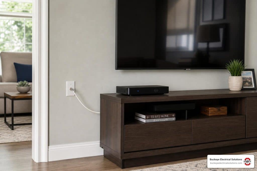
Understanding Burnham Boiler Thermostat Wiring and Controls
Burnham boiler thermostat wiring is one of the more common challenges Northeast Ohio homeowners run into when upgrading to a smart thermostat like a Nest or Ecobee. The process isn’t always straightforward — especially when your boiler lacks a C-wire, uses an older relay, or controls multiple heating zones.
Here’s a quick answer to what most people need to know:
How to wire a thermostat to a Burnham Series 2 boiler:
- R wire — connects to the 24VAC hot terminal (from the boiler transformer)
- W wire — connects to the heat call terminal (triggers burner or circulator)
- C wire — connects to the 24VAC common; on the Series 2, this can be tapped from the white wire in the 9-pin control harness
- Zone valve systems — require a separate 24V transformer rather than pulling C directly from the boiler control
Key point: Without a proper C-wire, most smart thermostats won’t power up reliably on a Burnham boiler. Getting this connection right is critical before anything else.
I’m Aaron, owner of Buckeye Electrical Solutions LLC here in Northeast Ohio — I’ve handled dozens of permitted low-voltage and boiler control projects, including Burnham boiler thermostat wiring upgrades across the region. Let’s walk through exactly how to do this correctly and safely.

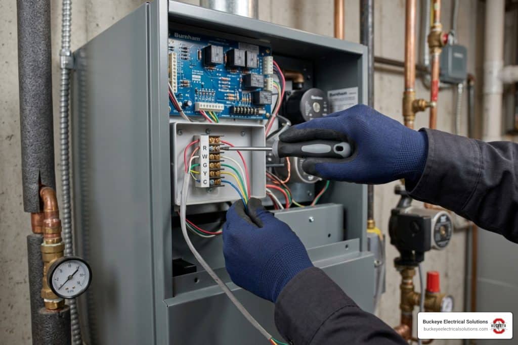
To successfully complete a Burnham boiler thermostat wiring project, it helps to understand the brain of your heating system. Modern Burnham Series 2 boilers utilize an integrated control system known as the Intelligent Hydronic Control (IHC), often powered by the Honeywell S9361A2072 control board.
Older gas boilers typically had simple, exposed terminal strips with simple “R” and “W” screws. However, the modern IHC system consolidates these connections into a multi-pin plug-and-play setup. On these boards, you will find a 9-pin control harness. This harness manages various internal safety limits, the gas valve, and the 24VAC power supplied by the boiler’s internal 40 VA transformer (such as the Honeywell AT140D1297).
The trick with these modern integrated controls is that while the transformer produces the 24VAC common side of the circuit (the “C” connection), there is rarely an external screw terminal labeled “C” on the outside of the jacket. If you look at the Burnham Corp. SERIES 2 Manual, you will see detailed schematics of the internal wiring, but finding where to physically land your smart thermostat’s common wire requires knowing where to tap into this 9-pin harness safely.
How to Connect a C-Wire to a Burnham Series 2 Boiler
Smart thermostats like Nest and Ecobee require a continuous loop of 24VAC power to keep their digital screens lit, run their Wi-Fi chips, and stay connected to your home network. Traditional mechanical thermostats only needed two wires (R and W) because they acted as simple on/off switches.
If you try to install a smart thermostat using only those two wires, the thermostat will attempt to “steal” power from the heating circuit when the boiler is off. This often causes the boiler’s control board to cycle rapidly, chatter, or fail to fire entirely.
To resolve this, we must establish a dedicated C-wire connection. According to verified industry solutions on forums like How to connect c-wire to Burnham Series 2 boiler?, the most reliable way to get a 24VAC common on a Burnham Series 2 boiler is to locate the 9-pin control harness on the S9361A2072 IHC module. Inside this harness, the white wire serves as the 24VAC grounded common side of the transformer circuit. By tapping into this wire, you can complete the electrical loop required to power your smart thermostat.
Step-by-Step Guide for Burnham Boiler Thermostat Wiring with a 9-Pin Harness
Before performing any electrical work, always turn off the main power switch to your boiler. Verify that the system is completely de-energized using a reliable digital multimeter. If you need a refresher on handling electrical connections safely, take a look at our guide on how to Upgrade Your Watts: What You Need to Know About Electrical Wiring.
Follow these steps to tap the 9-pin harness:
- Locate the IHC Module: Remove the front jacket cover of your Burnham Series 2 boiler to locate the Intelligent Hydronic Control board.
- Identify the Harness: Locate the 9-pin wiring harness plugged into the control board.
- Find the Common Wire: Look for the white wire inside the harness bundle. This white wire is typically bundled alongside two blue wires and serves as the 24VAC common.
- Prepare the Splice: Cut the white wire in a clean, accessible spot. Strip back approximately 1/4 inch of insulation from both cut ends, as well as from the end of the new C-wire running to your thermostat.
- Secure the Connection: Gather the two original white wire ends and your new thermostat C-wire. Twist them together securely using a properly sized wire nut.
- Double-Check Your Work: Ensure no bare copper is exposed outside the wire nut. Secure the wire nut with a wrap of electrical tape if desired.

Alternative Burnham Boiler Thermostat Wiring for Older R8285D Controls
If your Burnham Series 2 boiler was manufactured in the late 20th century, it may not feature the modern IHC module. Instead, many of these classic systems rely on a Honeywell R8285D control. This control is essentially an air-conditioning fan relay that manufacturers repurposed to run boiler circulator pumps.
When working with an R8285D control:
- The thermostat’s W (heat call) wire actually connects to the G terminal on the relay. This is because closing the circuit to “G” is what triggers the internal relay to start the circulator pump.
- The thermostat’s R wire connects to the R terminal on the control.
- To connect your C-wire, you must locate the common side of the built-in transformer. On the R8285D, the common side is typically connected to the metal chassis of the control or designated via a specific terminal screw shown on the casing’s wiring diagram.
Using a multimeter to verify 24VAC between your prospective C terminal and the R terminal is highly recommended before finalizing any connections. For a deeper dive into smart thermostat terminal designations and setups, check out our Wire Up Your World: A Smart Thermostat Installation Walkthrough.
Managing Zone Valves and External Transformers
If your home has multiple heating zones controlled by zone valves (such as Taco or Honeywell valves), your Burnham boiler thermostat wiring setup becomes slightly more complex.
A standard boiler-mounted transformer is rated for 40 VA. This is plenty of power to run the boiler’s internal safety controls and a single thermostat. However, if you attempt to power multiple smart thermostats and multiple zone valves from this single transformer, you will quickly overload it. Overloading the transformer will cause it to burn out or trip the boiler’s internal circuit protection.
As noted in community discussions like Adding C wire to Burnham 2 wire boiler – DoItYourself.com, the industry best practice is to install an external, dedicated 24V transformer (such as a Honeywell AT140D1297) specifically to power your zone valves and smart thermostats.
When wiring zone valves with an external transformer:
- Connect one side of the external transformer’s 24V output to the R terminal on all thermostats.
- Connect the other side of the external transformer’s 24V output to the C terminal on all thermostats, as well as to one side of each zone valve’s motor circuit.
- Use terminal blocks instead of messy wire nut bundles to keep these parallel connections organized and easy to troubleshoot.
Troubleshooting and Avoiding Common Boiler Wiring Mistakes
Adding a C-wire to a boiler system can be tricky. Even experienced DIYers can make mistakes that lead to system failures.
One of the most critical safety rules in hydronic heating control wiring is never to install auxiliary controls, switches, or limits in the grounded leg (common side) of the 24VAC circuit. Doing so can bypass safety limits and create a hazardous situation where the boiler burner could fire even if a safety limit is open. Always ensure that safety switches interrupt the hot side (R) of the low-voltage circuit.
If you complete your wiring and the thermostat fails to power up, the issue might not be at the boiler board itself. The power outlet feeding the boiler system or the transformer may have lost power. In these cases, remember: Outlet has no voltage; could indicate breaker, GFCI, switch, or wiring issue. Always trace the power from the main breaker panel down to the low-voltage terminals.
Below is a reference guide for troubleshooting common boiler thermostat wiring issues:
| Boiler Wiring Symptom | Likely Causes | Priority Level |
|---|---|---|
| Thermostat has no power / blank screen | Blown 3A fuse on IHC board; loose C-wire splice; tripped circuit breaker | High Priority |
| Boiler circulator runs constantly | Thermostat W wire shorted to R; improper wiring on older R8285D relay | Medium Priority |
| Boiler short cycles or chatters | Smart thermostat power-stealing without a connected C-wire | High Priority |
| Transformer is hot to the touch or buzzing | overloaded 40VA transformer due to multiple zone valves | High Priority |
Ohio Electrical Codes and Safety Standards for Boiler Installations
When performing any electrical work in Northeast Ohio, compliance with local building codes and safety standards is mandatory. Ohio’s 2023 National Electrical Code (NEC) adoption includes expanded GFCI protection requirements in several residential and commercial locations. While these rules are often situational rather than universal depending on the exact proximity to water or unfinished utility spaces, it is essential to ensure your boiler’s 120V power supply is fully code-compliant.
Additionally, hydronic heating systems rely on physical safety devices to prevent dangerous pressure build-ups. According to Burnham installation specifications:
- A safety relief valve (typically rated at 30 PSI standard) must be properly piped and installed in a vertical position with the discharge running near the floor.
- A low water cutoff (LWCO) must be installed above the boiler in the supply piping to ensure the burner shuts down immediately if the system loses water pressure.
Never bypass or jump out any of these safety devices during your thermostat installation. For a complete look at residential electrical safety, review The Ultimate Guide to Home Electrical Installation.
Frequently Asked Questions about Burnham Boiler Thermostat Wiring
Can I run a smart thermostat on a Burnham Series 2 boiler without a C-wire?
While some smart thermostats claim they can operate without a C-wire by “power stealing” or using internal batteries, we do not recommend this for Burnham boilers. Power stealing can cause the sensitive S9361A2072 IHC board to malfunction or cycle the gas valve rapidly. If running a physical C-wire through your walls is impossible, you should use a manufacturer-approved C-wire adapter (such as the Ecobee Power Extender Kit) or install a battery-powered thermostat.
What should I do if my smart thermostat has no power after wiring?
First, use a digital multimeter to check for 24VAC between the R and C terminals at the thermostat base. If you detect no voltage, check the 3-amp fuse on the boiler’s control board to see if it blew during installation. If the entire boiler seems dead, check the main service switch and circuit breaker. Outlet has no voltage; could indicate breaker, GFCI, switch, or wiring issue.
Do I need a separate transformer for my zone valves?
Yes, if you are running more than one or two zone valves alongside modern smart thermostats, you should install an external 24V transformer. The boiler’s built-in 40VA transformer is designed to handle the boiler’s internal operations and a single standard thermostat. Adding the electrical load of multiple smart screens and valve motors will quickly exceed this 40VA limit.
Conclusion
Upgrading your heating system with a smart thermostat is an excellent way to improve your home’s energy efficiency and comfort. However, handling Burnham boiler thermostat wiring requires precision, a solid understanding of low-voltage controls, and strict adherence to safety codes.
If you run into trouble, or if you prefer to have a licensed professional handle your boiler’s electrical integration, we are here to help. Buckeye Electrical Solutions is a trusted electrical contractor in Northeast Ohio with over 20 years of experience. We provide code-compliant, professional residential and commercial electrical services throughout the region. All of our service pricing and estimates are subject to change depending on local site conditions or AHJ requirements, ensuring you get an accurate, fair quote for your specific setup.
Ready to upgrade your home controls safely? Check out our step-by-step Wire Up Your World: A Smart Thermostat Installation Walkthrough or contact Buckeye Electrical Solutions today to schedule a professional installation!