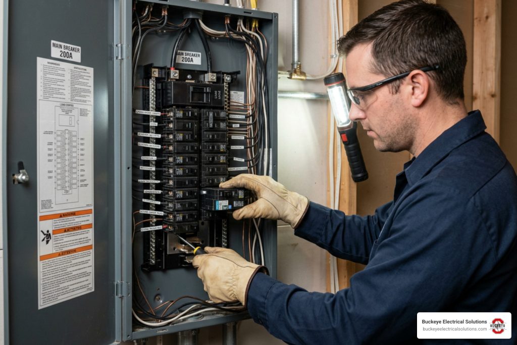
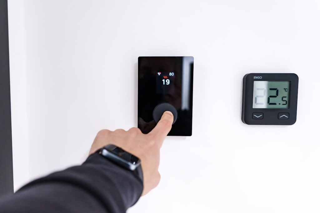
Why Getting Smart Thermostat Wiring Right Matters Before You Start
Understanding each smart thermostat wire connection can save you from a frustrating installation — or a thermostat that simply won’t work after you’ve already taken apart your old one.
Here’s a quick answer to what most people need to know:
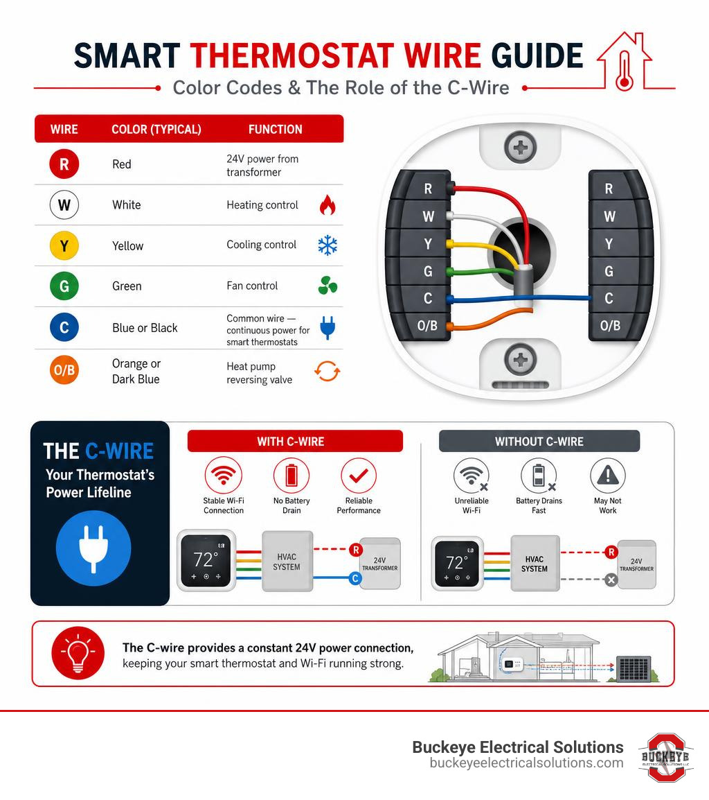
| Wire | Color (Typical) | Function |
|---|---|---|
| R | Red | 24V power from transformer |
| W | White | Heating control |
| Y | Yellow | Cooling control |
| G | Green | Fan control |
| C | Blue or Black | Common wire — continuous power for smart thermostats |
| O/B | Orange or Dark Blue | Heat pump reversing valve |
The most important thing to know: Most Wi-Fi-enabled smart thermostats need a constant power source — and that comes from the C-wire (common wire). Without it, your thermostat may lose Wi-Fi, drain batteries fast, or fail to turn on at all.
Homes built in recent decades often already have this wire in place. Older homes may not — but there are solutions that don’t require tearing open your walls.
This guide walks you through every step, from identifying what wires you have to connecting your new thermostat safely and correctly.
I’m Aaron, owner of Buckeye Electrical Solutions LLC and a master electrician with hands-on experience across residential electrical projects in Northeast Ohio — including smart thermostat wiring installations in everything from older ranch homes to newer construction. Whether you’re dealing with a missing C-wire or a heat pump system, I’ll walk you through exactly what to do.
Understanding Smart Thermostat Wiring and the Crucial C-Wire
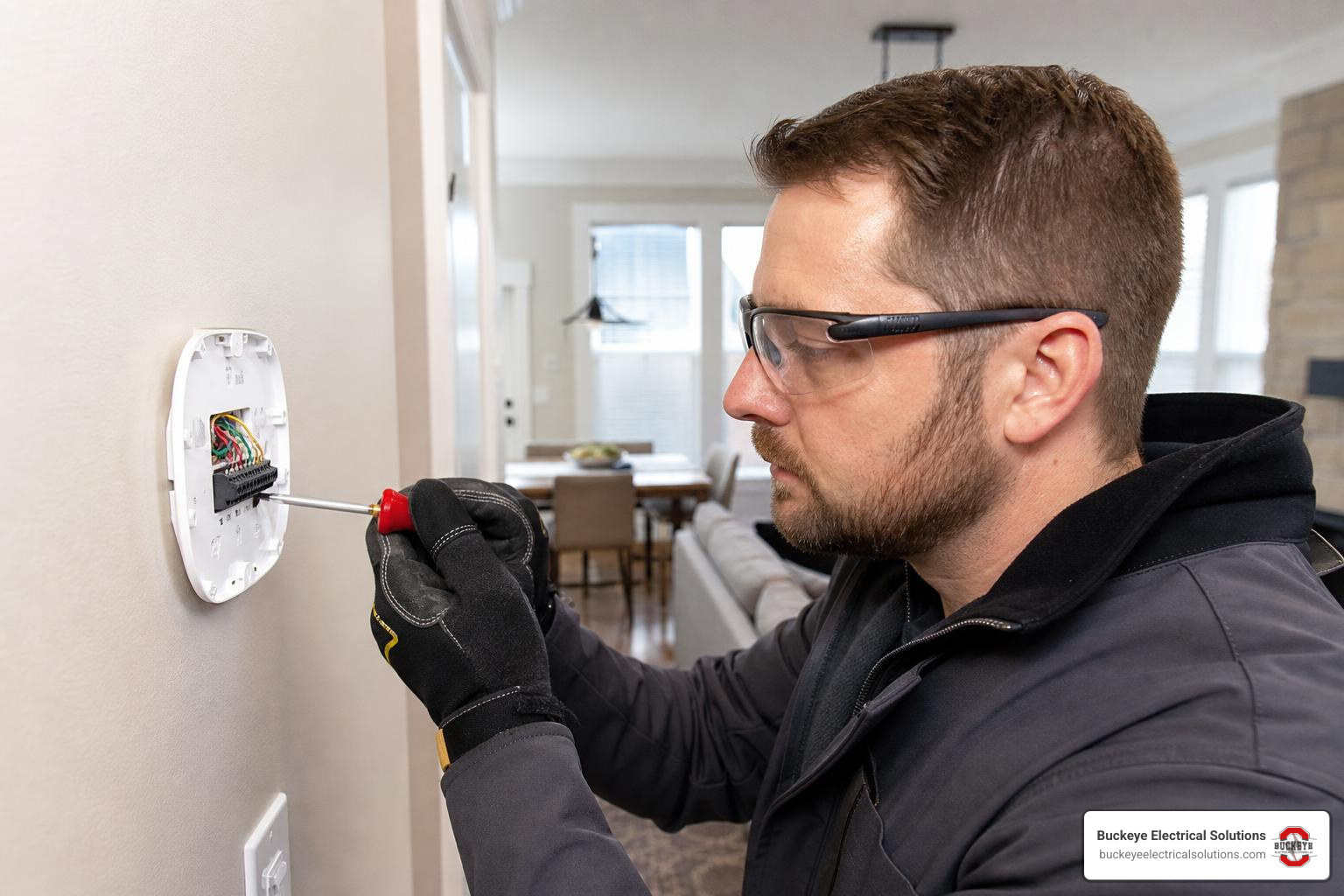
Most residential thermostats use low-voltage control wiring, commonly 24V AC, to tell your HVAC equipment when to heat, cool, run the blower fan, or switch a heat pump valve. The thermostat is basically the “traffic cop” for your comfort system.
Traditional thermostats did not need much power. Many older models were mechanical or battery-powered, so they could operate with only a few control wires. Smart thermostats are different. They run Wi-Fi radios, bright screens, processors, sensors, apps, and software updates. That little wall device is doing more than your old round thermostat ever dreamed of doing.
That is where the C-wire comes in.
A C-wire, or common wire, provides the return path for continuous 24V power from the HVAC transformer. It does not usually control heating or cooling by itself. Instead, it helps power the thermostat steadily. Google’s support article on the common or C wire explains this same idea: the C-wire is about consistent power, not directly turning equipment on and off.
If you are newer to electrical basics, our guide on home wiring fundamentals is a helpful next read.
Why Your Smart Thermostat Wiring Setup May Need a C-Wire
Your smart thermostat wiring setup may need a C-wire because smart thermostats need stable power for:
- Wi-Fi connection
- App control
- Touchscreen display
- Learning schedules
- Temperature sensors
- Firmware updates
- Voice assistant integrations
- System monitoring features
Some smart thermostats use “power sharing” or “power stealing,” which means they draw a small amount of power through heating or cooling circuits. This can work on many systems, but it is not perfect for every home.
Without a C-wire, you may notice:
- The thermostat battery drains quickly
- Wi-Fi drops offline
- The screen goes blank
- Heating or cooling delays occur
- The HVAC system behaves unpredictably
- Error messages appear during setup
- The thermostat reboots when equipment starts
In other words, the thermostat may act like it skipped breakfast. It is technically awake, but it is not ready to do its job.
Many Wi-Fi and color touchscreen thermostats require a C-wire. Some models can work without one in certain systems, but heat-only, cool-only, heat pump, and zone-controlled systems often need either a C-wire or a manufacturer-approved power accessory.
Standard Thermostat Wire Colors and Functions
Thermostat wire colors are helpful, but they are not law. We always verify wires by terminal labels, not color alone. A previous installer may have used whatever conductor was available.
Still, most residential systems follow these common patterns:
| Terminal | Typical Wire Color | What It Usually Does |
|---|---|---|
| R, Rc, Rh | Red | 24V power from transformer |
| C | Blue or Black | Common side of transformer for continuous power |
| W, W1 | White | First-stage heating |
| W2, Aux | Brown, White, or other | Second-stage heat or auxiliary heat |
| Y, Y1 | Yellow | First-stage cooling or compressor |
| Y2 | Light Blue or other | Second-stage cooling |
| G | Green | Indoor blower fan |
| O/B | Orange or Dark Blue | Heat pump reversing valve |
| E | Brown or other | Emergency heat on some heat pumps |
| HUM/DEHUM | Varies | Humidifier or dehumidifier control |
A few important notes:
- Red may connect to R, Rc, or Rh depending on the system.
- Some thermostats use a jumper between Rc and Rh.
- O/B wiring matters a lot on heat pumps because it controls whether the reversing valve energizes in heating or cooling.
- Blue is often the C-wire, but not always.
- For any smart thermostat wire, the terminal label matters more than the jacket color.
- If you see thick wires or wire nuts behind a thermostat, stop and verify voltage. You may have a line-voltage thermostat, which is a different installation.
Assessing Your Existing HVAC System and Wiring Compatibility
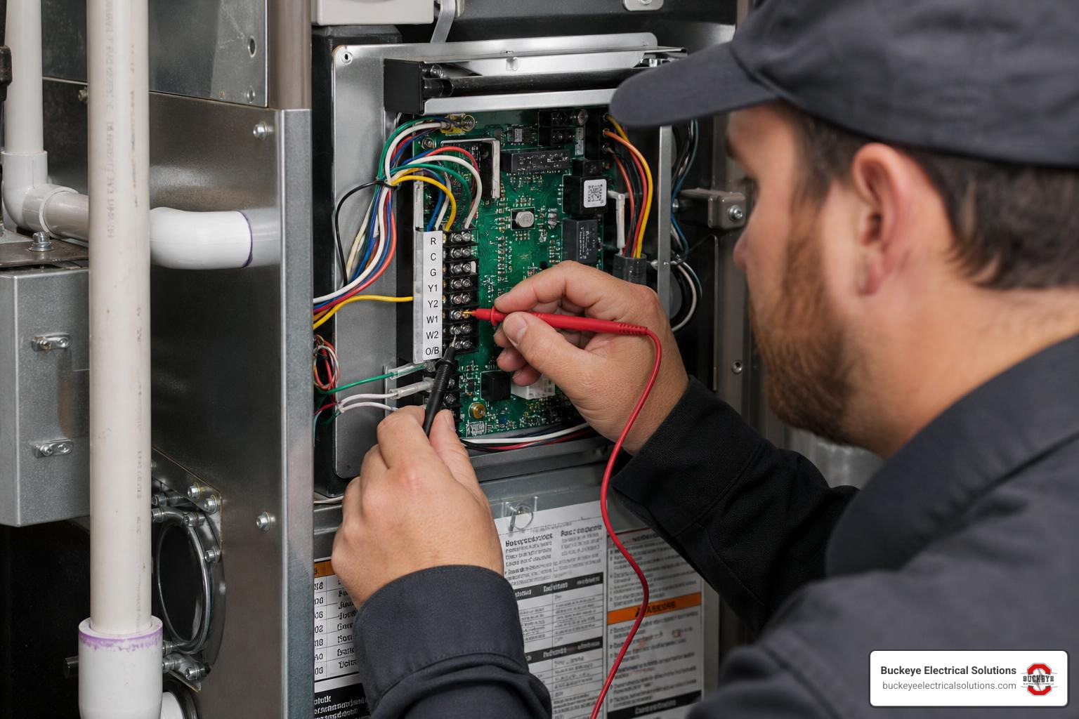
Before wiring a smart thermostat, identify two things:
- What type of HVAC system you have
- What wires are actually available at the thermostat and equipment control board
This is where many DIY projects get sideways. A thermostat may look compatible based on the wall wiring, but the HVAC control board tells the fuller story.
Many smart thermostats work with standard 24V systems, including gas furnaces, electric furnaces, oil systems, forced air systems, heat pumps, and radiant systems. For example, the Nest Learning Thermostat 4th gen specifications state that it works with most 24V systems and often operates without a C-wire through power sharing, though some systems still need a C-wire or power connector.
The key phrase is “most 24V systems.” Not every system is standard.
How to Identify Your HVAC System Type
Here are the common system types we see in Ohio homes.
Conventional heating and cooling
This is common in Northeast Ohio. You may have a gas furnace with central air conditioning. Typical wires include R, W, Y, G, and sometimes C.
- R powers the thermostat
- W calls for heat
- Y calls for cooling
- G runs the fan
- C provides common power
This setup is often smart-thermostat friendly if a C-wire is available.
Heat-only system
A heat-only system may have just R and W wires. Older boilers and furnaces often fall into this category. These systems are simple, but many smart thermostats need extra power because there is no cooling wire to help with power sharing.
A C-wire, power adapter, or new thermostat cable may be needed.
Cool-only system
A cool-only system may have R, Y, and G, but no W. Some smart thermostats require a C-wire for these systems because there are fewer control paths available.
Heat pump system
A heat pump uses a compressor for heating and cooling. It usually has an O/B reversing valve wire. It may also have Aux or E heat.
Heat pumps need careful compatibility checks because:
- O/B settings must be configured correctly
- Auxiliary heat must be wired properly
- Dual-fuel systems need the right controls
- Some smart thermostats require a C-wire for stable operation
If the reversing valve is misconfigured, your system may heat when it should cool, which is a very Ohio-in-July problem nobody wants.
Zone-controlled system
Zoned HVAC uses dampers and a zone control panel. These systems often require a C-wire or power accessory because the thermostat interacts with the zone panel instead of a simple furnace board.
Line-voltage system
Some electric baseboard or wall heater thermostats use 120V or 240V wiring. These are not the same as 24V smart thermostat systems.
Signs you may have line voltage:
- Thick wires, often 12 or 14 gauge
- Wire nuts in the thermostat box
- Labels showing 120V or 240V
- No low-voltage terminal letters like R, C, W, Y, G
If you find line voltage, do not connect a standard smart thermostat. Call a qualified electrician.
Checking Existing Smart Thermostat Wiring
To check whether each smart thermostat wire you need is available, start at the thermostat.
- Turn off power to the HVAC system.
- Remove the thermostat faceplate.
- Take a clear photo of the wiring.
- Look for a wire connected to the C terminal.
- Look for an unused wire tucked behind the wall.
- Compare the thermostat wiring to the HVAC control board.
A home may have a spare conductor in the cable bundle that is not connected at either end. This is common when a 5-conductor or 7-conductor thermostat cable was installed but the old thermostat only needed four wires.
If you find an unused wire behind the thermostat, do not assume it is a working C-wire. It must also be connected to the C terminal at the furnace, air handler, or zone panel.
Homes built in recent decades often have enough thermostat conductors for smart thermostat upgrades, but we still verify every time. Age is a clue, not a guarantee.
Step-by-Step Guide: How to Wire a Smart Thermostat
The steps below apply to many standard 24V thermostat installations. Always follow the manufacturer’s instructions for your exact thermostat and HVAC system.
If anything looks unusual, stop. Low-voltage thermostat wiring is safer than line voltage, but a wrong connection can damage the thermostat, transformer, control board, or HVAC equipment.
For testing basics, see our guide to electrical testers and how to use them.
Step 1: Power Down and Safety First
Turn off power before touching any thermostat wires.
You can usually shut power off at:
- The HVAC service switch near the furnace or air handler
- The circuit breaker feeding the HVAC equipment
- Both, if you want to be extra careful
Do not rely only on turning the thermostat “off.” That does not necessarily remove power from the wiring.
After shutting power down:
- Confirm the display is off.
- Use a tester if you are comfortable doing so.
- Avoid letting bare wires touch each other.
- Keep wires from falling into the wall.
Thermostat wiring is usually 24V, but shorting R to C can blow a fuse or damage a transformer. A tiny spark can turn into a much bigger headache.
Step 2: Label and Disconnect Old Wires
Before removing anything, take photos.
Take:
- A close-up photo of the thermostat terminals
- A wider photo showing the cable and wall
- A photo of any jumper wires
- A photo of the HVAC control board if accessible
Then label each wire by the terminal it connects to, not by color.
For example:
- Red wire on R gets labeled R
- White wire on W gets labeled W
- Green wire on G gets labeled G
- Blue wire on Y gets labeled Y if that is where it was connected
That last example is why color alone can fool you.
After labeling, loosen the terminal screws or release the push connectors and gently remove each wire. Bend the wires slightly outward so they do not slip into the wall.
Step 3: Mount the New Base Plate
Remove the old thermostat base and position the new smart thermostat base plate.
Check:
- Is the base level?
- Are the wires centered through the opening?
- Will the anchors hold securely?
- Do you need a trim plate to cover old paint or wall marks?
Many smart thermostats include a trim plate. It is optional, but it can make the finished installation look cleaner, especially if the old thermostat was larger.
When drilling anchors, be careful not to damage the thermostat cable behind the wall. This is not the time to discover your drill has a dramatic personality.
Step 4: Connect the Thermostat Wires
Connect each labeled wire to the matching terminal on the new thermostat base.
Common connections include:
| Old Terminal | New Terminal | Notes |
|---|---|---|
| R | R, Rc, or Rh | Follow thermostat instructions |
| C | C | Common wire for power |
| W | W or W1 | Heat call |
| Y | Y or Y1 | Cooling/compressor |
| G | G | Fan |
| O/B | O/B | Heat pump reversing valve |
| Aux/E | Aux, W2, or E | Heat pump backup or emergency heat |
Important connection tips:
- Strip only the amount of insulation required.
- Insert copper fully into push terminals.
- No bare copper should stick out beyond the terminal.
- Tug gently to confirm the wire is secure.
- Do not connect unused wires unless instructed.
- Do not guess with O/B, Aux, E, or accessory wires.
If you are adding a C-wire using an unused conductor, connect that conductor to C at both the thermostat and the HVAC control board. If the C terminal is already occupied, multiple low-voltage conductors may be allowed depending on the terminal design, but the connection must be secure and manufacturer-approved.
Step 5: Attach the Faceplate and Power Up
Once wiring is complete:
- Attach the thermostat faceplate.
- Restore power at the breaker or HVAC switch.
- Wait for the thermostat to boot.
- Follow the setup prompts.
- Select the correct HVAC system type.
- Test heating, cooling, fan, and heat pump modes if applicable.
During setup, many smart thermostats run a compatibility or power test. Pay attention to warnings about missing C-wires, low power, or equipment configuration.
After installation, monitor the system for a few days. If the thermostat loses Wi-Fi, restarts, displays power errors, or behaves strangely, the wiring or power setup may need adjustment.
For a broader smart home wiring perspective, our article on smart 3-way switch wiring shows how important correct conductors are for modern connected devices.
No C-Wire? Alternative Solutions for Modern Thermostats
No C-wire? Do not panic. This is one of the most common smart thermostat installation issues we see.
You have several reliable options:
- Use an unused wire as the C-wire
- Repurpose the G-wire
- Install a C-wire power adapter kit
- Run a new dedicated thermostat cable
For more on wiring upgrade considerations, see our guide to electrical wiring upgrades.
| Solution/Issue | likely causes | priority level |
|---|---|---|
| Use an unused wire as C | Extra conductor exists in thermostat cable but is not connected at the HVAC control board | High if available |
| Repurpose G-wire as C | No spare conductor, but homeowner can give up independent fan control | Medium |
| Install C-wire power adapter kit | No spare wire and G-wire conversion is not preferred | High for many smart thermostats |
| Run new thermostat cable | Existing cable has too few conductors or wiring is damaged | High for long-term reliability |
| Thermostat loses Wi-Fi or reboots | Weak power, missing C-wire, loose terminal, or incompatible power sharing | High |
| HVAC fuse blows after wiring | Shorted R to C, crossed conductors, improper wiring, or damaged low-voltage cable | Urgent |
| Outlet has no voltage; could indicate breaker, GFCI, switch, or wiring issue | Power source or nearby service receptacle issue found during troubleshooting | Medium to High |
| Heat pump blows hot in cooling mode | O/B setting mismatch or reversing valve wiring issue | High |
| Fan will not run independently | G-wire was repurposed as C or fan terminal is not connected | Medium |
Option A: Repurposing the G-Wire
The G-wire controls the indoor blower fan. In some installations, it can be repurposed as a C-wire. This is often called a G-to-C conversion.
Basic concept:
- Move the G wire from G to C at the thermostat
- Move the same wire from G to C at the HVAC control board
- Add a jumper at the HVAC equipment from Y to G in certain conventional systems, if allowed by the equipment and thermostat instructions
This can allow the blower to run automatically during cooling calls, but you may lose independent fan control from the thermostat. That means you may not be able to run “fan only” mode.
G-wire repurposing is not right for every system. It is generally not recommended for heat pumps, zone systems, or systems where fan control is more complex. We treat it as a practical workaround, not the gold standard.
Option B: Installing a C-Wire Power Adapter Kit
A C-wire adapter, power connector, or common wire maker kit provides thermostat power when a dedicated C-wire is missing. These kits are often installed at the HVAC control board and use the existing thermostat cable in a different way.
Depending on the model, the kit may include:
- A small adapter module
- Push terminals
- Wire leads
- Diodes or signal-splitting components
- Mounting hardware
- Wiring labels
A typical adapter installation involves:
- Turning off HVAC power
- Opening the furnace or air handler access panel
- Locating the low-voltage control board
- Identifying R, C, W, Y, and G terminals
- Connecting the adapter according to the thermostat manufacturer’s diagram
- Reconnecting thermostat wires as instructed
- Restoring power and testing operation
Do not mix instructions between thermostat brands or adapter kits. A power connector designed for one thermostat may not wire the same way as another.
Also, some kits are not compatible with two-wire systems or heat-only systems. Always check the manufacturer’s compatibility chart before buying.
Option C: Running a New Dedicated Wire
The most reliable long-term solution is often running a new thermostat cable with enough conductors.
For many modern systems, we prefer enough conductors for:
- R
- C
- W
- Y
- G
- O/B if heat pump
- Aux or W2 if needed
- Extra conductors for future equipment
Running new cable may involve wall fishing, basement or attic access, and careful routing to the HVAC equipment. In some homes, it is straightforward. In others, finished walls, tight chases, or older construction make it more involved.
Pricing for this work can vary based on site conditions, cable routing, wall access, HVAC equipment location, and any local authority having jurisdiction requirements. We avoid giving fixed numbers without seeing the home because every Ohio house likes to keep at least one secret.
Frequently Asked Questions About Smart Thermostat Wiring
Can I install a smart thermostat if my home only has two wires?
Sometimes, but it depends on the thermostat and the HVAC system.
Two-wire systems are usually heat-only systems with R and W. Many older furnaces and boilers use this setup. A basic battery-powered thermostat may work fine with two wires, but many smart thermostats need more power than those two wires can provide.
Possible solutions include:
- Choosing a smart thermostat specifically rated for two-wire heat-only systems
- Adding a C-wire if the HVAC equipment has a C terminal
- Installing a manufacturer-approved power adapter
- Using an external 24V transformer where allowed by the thermostat design
- Running a new thermostat cable
Be careful with external transformers. They must be wired correctly and compatible with the thermostat and HVAC controls. Incorrect transformer wiring can damage equipment or create unsafe conditions.
If your two-wire system controls a boiler, zone valve, or older relay, we recommend professional evaluation before installing a smart thermostat.
What should I do if my smart thermostat loses connection or power?
A smart thermostat that loses power or Wi-Fi may have a wiring, power, or compatibility issue.
Start with these checks:
- Confirm the HVAC breaker and service switch are on.
- Make sure the furnace door panel is fully seated, since many systems have a safety switch.
- Check whether the thermostat is properly snapped onto its base.
- Verify each wire is fully inserted.
- Look for thermostat error messages.
- Confirm the C-wire is connected at both ends.
- Check for a blown low-voltage fuse on the HVAC control board.
- Review the thermostat app’s power readings if available.
Common likely causes include:
- Loose C-wire connection
- Missing C-wire
- Weak power sharing
- Tripped breaker
- Blown control board fuse
- Incorrect Rc/Rh configuration
- HVAC transformer issue
- Wi-Fi router or signal issue
- Incompatible HVAC system
Some smart thermostats include system health or power monitoring features. These can help identify low power, delayed heating, or equipment behavior that needs service.
If the thermostat worked for a while and then started failing, do not assume the thermostat is bad. A loose wire, weak transformer, dirty furnace switch, or control board issue can produce similar symptoms.
Does Ohio’s adoption of the 2023 NEC impact thermostat wiring?
For most standard residential smart thermostat wiring, the thermostat conductors are typically low-voltage Class 2 control circuits. These are not treated the same as 120V or 240V branch circuits.
That said, Ohio’s 2023 NEC adoption can affect related electrical work in situational ways. It includes expanded GFCI requirements in several locations, but whether a specific rule applies depends on the equipment, location, installation details, and local interpretation. This matters more when a thermostat project involves nearby receptacles, HVAC service outlets, condensate pumps, equipment disconnects, or other line-voltage work.
A few practical points:
- Standard thermostat wire is usually low voltage.
- HVAC equipment still has line-voltage power feeding it.
- Service receptacles, GFCI protection, disconnects, and equipment wiring must meet applicable code.
- Local interpretation can vary by authority having jurisdiction.
- If a smart thermostat installation expands into new wiring, receptacles, or equipment changes, code review matters.
When we work on Ohio homes, we look at the whole installation, not just the thermostat on the wall. The small device is low voltage, but it connects to equipment that absolutely is not.
Conclusion
Wiring a smart thermostat can be manageable when you understand the basics: identify your HVAC system, verify each wire by terminal, confirm whether you have a C-wire, shut power off, and follow the thermostat’s setup instructions carefully.
The C-wire is the big player in most modern installs because it gives the thermostat continuous power for Wi-Fi, touchscreen features, app control, and reliable operation. If your home does not have one, you still have options: an unused conductor, a G-wire conversion, a C-wire adapter, or a new dedicated thermostat cable.
At Buckeye Electrical Solutions, we help homeowners across Northeast Ohio upgrade smart thermostats safely and cleanly. With extensive residential electrical experience, we understand both the low-voltage thermostat side and the line-voltage equipment side that supports it.
If you want help choosing, wiring, or troubleshooting your thermostat, we are ready to help. You can schedule a smart thermostat installation walkthrough and let us make sure your smart thermostat is actually smart enough to turn on.