Step 1: Prioritize Safety and Prepare Your HVAC System
Thermostat wiring connections are the low-voltage wires that link your thermostat to your HVAC system, telling it when to heat, cool, or run the fan. Most residential systems use 24V control circuits and follow a standard terminal labeling system.
Quick Reference: Standard Thermostat Wire Terminals
| Terminal | Common Wire Color | Function |
|---|---|---|
| R | Red | 24V power from transformer |
| Rc | Red | Power — cooling transformer |
| Rh | Red | Power — heating transformer |
| W / W2 | White | Heat call (stage 1 / stage 2) |
| Y / Y2 | Yellow | Cooling / compressor |
| G | Green | Fan / blower |
| C | Blue or Black | Common side of the 24 VAC transformer; used with R to provide continuous thermostat power. |
| O/B | Orange or Blue | Heat pump reversing valve |
| E | — | Emergency heat |
| AUX | — | Auxiliary heat |
Wire colors are a convention, not a guarantee — identify wires by their terminal letter, not color alone.
Terminal meanings and wire colors vary by thermostat and HVAC manufacturer. Always confirm wiring with the thermostat and HVAC-equipment installation manuals.
Most homes use a 5-wire configuration, but systems can range from two wires for heating-only systems to ten or more wires for advanced multi-stage or commercial setups. Correct connections help the HVAC system respond reliably and reduce the risk of blown fuses or damaged control equipment.
This guide walks through the process in five practical steps so you know what you are looking at before you touch anything. I’m Aaron, owner of Buckeye Electrical Solutions LLC in Northeast Ohio, and I’ve worked on thermostat wiring connections across dozens of permitted residential and commercial projects throughout the region. Whether you’re upgrading to a smart thermostat or troubleshooting an existing system, the steps below give you a clear, safety-first path forward.
Before you strip a wire or loosen a terminal screw, safety comes first. Thermostat wiring operates on low-voltage 24VAC, but the equipment it connects to may run on standard 120V or 240V household electricity. A short circuit in low-voltage control wiring can blow the small fuse on a furnace control board, shut down the system, or damage sensitive components.
Locate your home’s main electrical panel and turn off the applicable circuit breaker for the heating and cooling equipment. If you have separate heating and cooling systems, you may need to turn off more than one breaker.
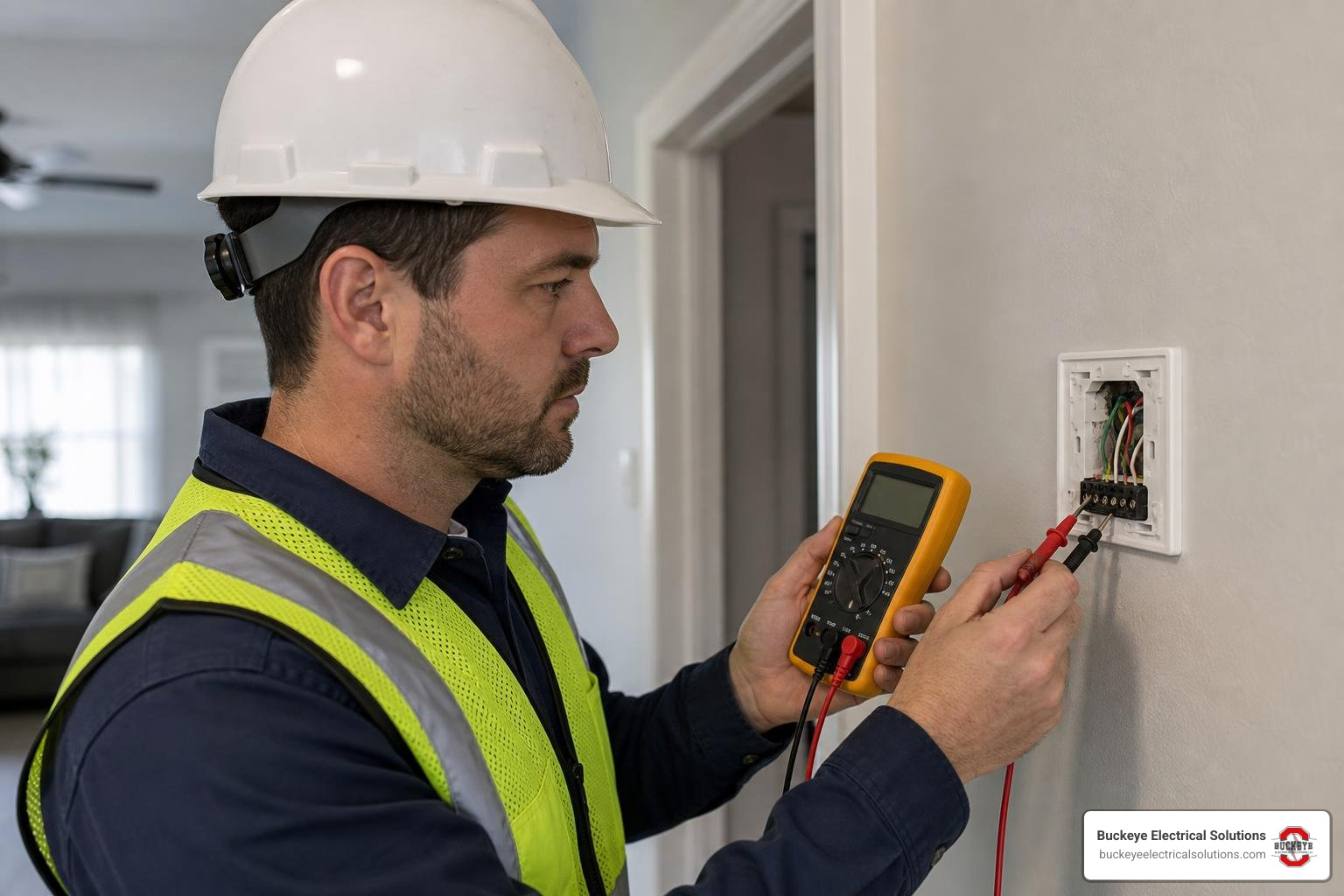
If you are not trained to test HVAC controls safely with a multimeter, do not probe thermostat terminals. Turn off applicable equipment power, photograph and label the wiring, and contact an HVAC professional if anything is unclear.
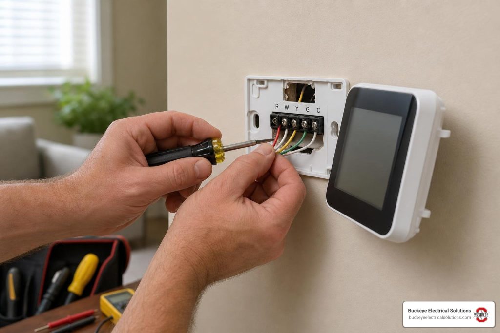
Once equipment power is off, gently pull the thermostat body off its sub-base to expose the wiring. Take a clear reference photo of the current connections, making sure terminal letters such as R, W, Y, G, and C are visible. Use masking tape or the labeling stickers provided with your new thermostat to label each wire based on the terminal letter it is currently connected to. Do not label by color alone, because previous installers may not have followed standard color conventions. Wrap the labeled wires around a pencil or pen to keep them from slipping back into the wall cavity. While low-voltage DIY adjustments are common, unpermitted work can complicate claims if electrical issues arise later, so proceed carefully or consult a licensed professional.
Step 2: Decode the Standard Thermostat Wiring Connections
Understanding how control signals travel through your walls can take the mystery out of thermostat wiring connections. Think of your thermostat as a set of automated switches. The red power wire (R) brings 24VAC from the HVAC transformer to the thermostat. When the thermostat calls for heating, cooling, or air circulation, it closes a switch and sends 24V current back down the appropriate wire to activate the equipment.
Thermostat wiring typically uses solid-core copper wire from 18 AWG to 24 AWG, with 18 AWG common in residential installations. Solid-core wire helps create clean, low-resistance connections in many modern thermostat terminals.
For power distribution, you may see terminals labeled R, Rc, and Rh. In many single-transformer systems, one red wire powers both heating and cooling controls. If your old thermostat has Rc and Rh terminals, follow the new thermostat manufacturer’s instructions. Do not add, remove, or move a jumper unless documentation confirms the system configuration. For more detail on thermostat wiring arrangements, refer to the Thermostat Wiring: An In-Depth HVAC Guide.
Understanding Low-Voltage Thermostat Wiring Connections for Boilers and Furnaces
Older heating-only systems and hydronic boiler setups may use simplified 2-wire or 3-wire configurations, but boiler and hydronic controls vary. Some use 24 VAC switching, while others use dry contacts or proprietary control logic. Confirm the boiler and control-board documentation before adding a smart thermostat or power adapter.
For a complete breakdown of hydronic heating controls, explore our guide on How to Connect a Thermostat to a Boiler Without a Meltdown. If you have a Burnham boiler system in your Northeast Ohio home, Sparking Joy: The Ultimate Guide to Burnham Boiler Thermostat Wiring may also help. European-style cylinder or storage systems can involve specialized terminal arrangements, as covered in The Ultimate Drayton Cylinder Thermostat Wiring Guide.
Standard 4-Wire and 5-Wire Thermostat Wiring Connections
The most common setup found in many Ohio homes is the 4-wire or 5-wire configuration. A standard 4-wire system includes:
- R: 24VAC Power
- W: Heating (Furnace)
- Y: Cooling (Air Conditioner Compressor)
- G: Fan (Blower Motor)
A 4-wire system can run many standard programmable thermostats, but it lacks a dedicated common wire for continuous thermostat power. A 5-wire configuration adds the C wire, which is the common side of the 24-volt transformer circuit. Used with R, it provides continuous 24VAC power for Wi-Fi radios, touchscreens, and smart sensors.
Depending on the thermostat and HVAC equipment, operation without a dedicated C wire can cause compatibility issues, relay chatter, short cycling, or unreliable performance. To understand standard 5-wire schematics, review the official How to Wire a Thermostat | Thermostat Wiring Diagram resource.
Step 3: Map Out Your Specific Wire Configuration (2-Wire to Multi-Core)
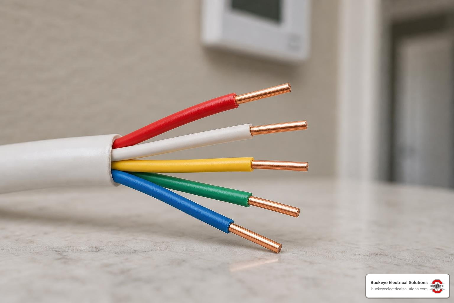
When running new thermostat lines, selecting the right multi-core cable helps preserve future compatibility. Thermostat cables are sold by gauge and core count, such as 18/5 (18 AWG, 5 conductors) or 18/8 (18 AWG, 8 conductors).
Your current HVAC system might only require four wires, but pulling a larger cable can be a useful planning estimate during renovation or repair. For example, installing an 8-core cable may leave extra conductors for future heat pump retrofits, whole-home humidifiers, or multi-stage equipment upgrades without fishing new wire through finished drywall later.
If you want to build your residential wiring knowledge, see Power Up Your Knowledge: A Beginner’s Guide to Home Wiring.
Typical configurations include:
- 2-Core (18/2): Often used for heating-only systems, such as some boilers or millivolt wall heaters.
- 3-Core (18/3): May be used for heating-only systems where a smart thermostat needs a C wire, or for simple cooling-only setups.
- 4-Core (18/4): Common for basic, single-stage heating and cooling systems without a C wire.
- 5-Core (18/5): Common for single-stage systems using R, W, Y, G, and C.
- 6-Core to 8-Core (18/6 or 18/8): May be needed for heat pumps, multistage equipment, zoning, humidifiers, or other accessories.
Step 4: Address Heat Pumps, Reversing Valves, and Dual-Fuel Systems
Heat pumps require a different wiring approach because they use the same compressor loop for heating and cooling. To switch modes, a heat pump uses a reversing valve controlled by the O/B terminal on the thermostat.
Set the O/B configuration according to the outdoor-unit and thermostat documentation. Reversing-valve operation varies by equipment design; do not choose O or B based only on wire color or brand.
Connecting both an O and a B wire to the same thermostat can be an error; connect only the active reversing-valve wire to the O/B terminal and configure the thermostat software to match the documented system setup.
Because heat pumps can lose efficiency during sub-zero Northeast Ohio winter spells, they are often paired with auxiliary heating elements or a gas/oil furnace in a dual-fuel system. In these setups, the thermostat may use the AUX or W2 terminal to engage backup heat when the outdoor temperature drops below a configured threshold.
In a dual-fuel system, staging must be configured so the heat-pump compressor is locked out when the fossil-fuel furnace operates, unless the equipment manufacturer specifically permits another sequence. For smart staging instructions, refer to the Learning Thermostat Installation Guide.
Step 5: Troubleshoot Non-Standard Wires and Avoid Common Mistakes
If you remove your old thermostat and find non-standard wire colors, faded insulation, or unfamiliar terminal labels, do not guess where they go. Many older systems or custom installations do not follow standard color conventions. Trace the wires back to the control board inside the furnace or air handler when possible; the labeled HVAC control-board terminals can show where each colored wire connects.
Unfamiliar terminal labels or numbered terminals may indicate a communicating or proprietary system. Confirm the equipment model and manual before installing a conventional or retail smart thermostat.
Common wiring mistakes include:
| Symptom / Mistake | Likely Causes | Priority Level |
|---|---|---|
| Blower fan runs continuously | G wire shorted to R, or thermostat fan setting set to “On” instead of “Auto” | Medium |
| System blows cold air in heat mode | Reversing valve (O/B) configuration incorrect; incorrect default state selected | High |
| Thermostat screen is blank | Blown low-voltage fuse on control board, tripped breaker, service switch off, or equipment power issue | High |
| Heating turns on during cooling call | W and Y wires reversed at the thermostat terminals | High |
If your thermostat screen is blank or the system will not power up, the thermostat may not be the source of the problem. Many modern high-efficiency furnaces are powered through a nearby service switch, receptacle, or protected circuit, and a tripped safety device can cut power to the HVAC control board. If you are tracking down an elusive power issue, our guide on Don’t Get Zapped: Expert Advice for Electrical Troubleshooting offers practical advice for locating common residential electrical faults.
Frequently Asked Questions About Thermostat Wiring Connections
How do I identify thermostat wires if the colors do not match the standard code?
If your wire colors do not match the standard color code, ignore the colors and focus on terminal designations. Before disconnecting your old thermostat, take clear reference photos and apply wire labels based on the letters on the old sub-base. If the wires are dirty or faded, clean the insulation with a damp cloth to identify them, or trace the cable back to the furnace control board to see where each wire lands.
When is a C wire required, and what are my options if my wall lacks one?
A C (common) wire is typically required for smart thermostats to provide continuous 24VAC power for Wi-Fi, touchscreens, and smart features. A manufacturer-compatible power connector, C-wire adapter, or new thermostat cable may be an option, but compatibility depends on the thermostat and HVAC configuration. Verify compatibility before purchase.
How do Ohio electrical codes and NEC standards apply to thermostat installations?
In Ohio, thermostat wiring is generally treated as low-voltage Class 2 control wiring, but code and permit requirements depend on the equipment, scope of work, and local authority having jurisdiction.
Like-for-like thermostat replacement is often straightforward, but permit and code requirements depend on the scope of work and the local authority having jurisdiction—especially when work affects line-voltage HVAC circuits, equipment wiring, or new cable routing. Ohio’s 2023 NEC adoption includes expanded GFCI requirements in several locations, so specific rules can be situational rather than universal and subject to AHJ approval. To learn more about national standards, read The NEC Book Bible.
Conclusion
Understanding your thermostat wiring connections helps improve comfort, efficiency, and HVAC reliability. Whether you are installing a programmable thermostat or integrating a smart home device, a systematic, safety-first approach helps the system operate as intended. If you are ready to install a new device, see Wire Up Your World: A Smart Thermostat Installation Walkthrough.
Many basic thermostat upgrades are straightforward, but heat pumps, boilers, dual-fuel systems, communicating equipment, missing C wires, and unclear wiring often benefit from professional support. Buckeye Electrical Solutions brings over 20 years of residential and commercial electrical experience to homes across Northeast Ohio. If you are unsure about your wiring, need new thermostat cable, or want help configuring smart home technology, contact us for a professional, code-conscious installation.