What You Need to Know About Bathroom Fan Wiring with a Light
Bathroom fan wiring is one of those home electrical projects that can be tricky if not wired correctly — but with the right cable, the right circuit setup, and a clear plan, it’s very manageable.
Here’s a quick answer to what most homeowners are looking for:
| What You Want | What You Typically Need |
|---|---|
| Fan and light on one switch | 14/2 NM-B cable |
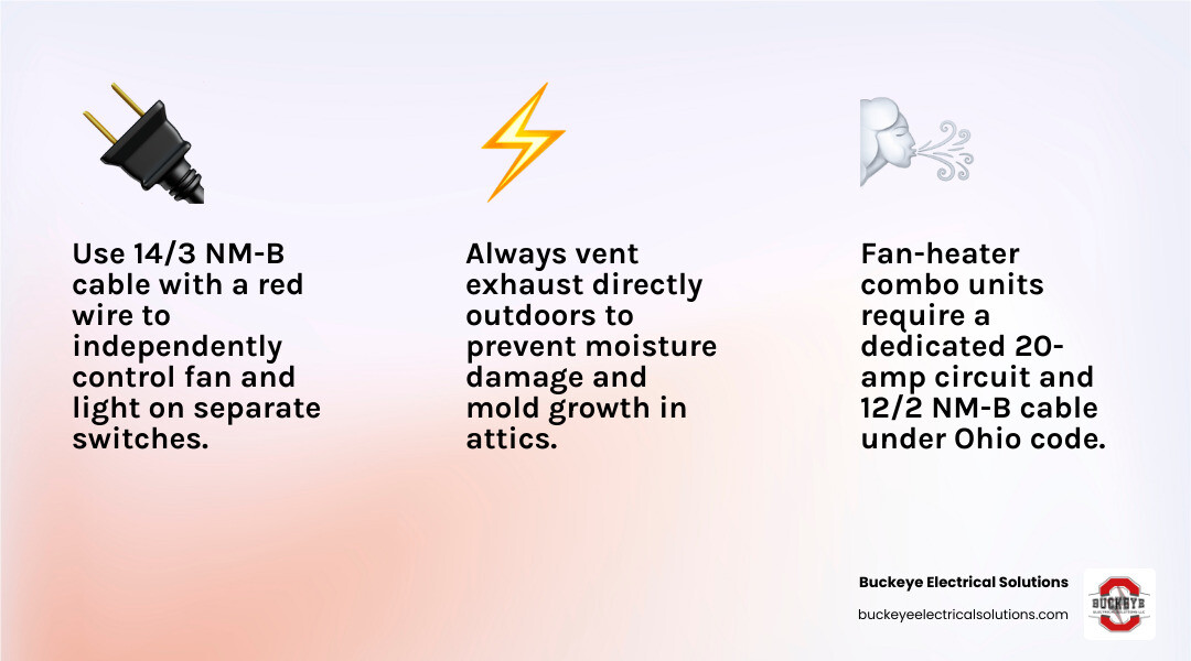
| Fan and light on separate switches | 14/3 NM-B cable typically needed (black, red, white, ground) |
| Fan + heater combo unit | Dedicated 20-amp circuit; 12/2 NM-B cable |
| GFCI protection | May be required depending on your specific setup and location |
| Exhaust venting | Should vent directly outdoors (roof, sidewall, or gable) |
A few key things to keep in mind before you start:
- 14/3 cable gives you a second switched hot (the red wire), which lets you control the fan and light independently. The exact wiring depends on your switch configuration.
- Fan-heater and heat-lamp combo units draw significantly more power and typically require a dedicated 20-amp circuit.
- Bathroom fans should vent to the outside — venting into an attic can trap moisture and create conditions that may lead to mold or structural damage over time.
- Most fan/light combo units share a single neutral wire, though this can vary depending on the unit and control type.
A bathroom without proper ventilation doesn’t just feel stuffy — it can create conditions where moisture might quietly damage walls, ceilings, and finishes over time.
I’m Aaron, owner of Buckeye Electrical Solutions LLC and a master electrician with experience overseeing dozens of permitted residential projects across Northeast Ohio, including bathroom fan wiring installations in homes of all ages. In this guide, I’ll walk you through everything from choosing the right cable to making safe, code-aware connections.
Explore more about bathroom fan wiring with light:
Planning Your Bathroom Ventilation Upgrade
Before we strip a single wire or open a junction box, it is highly recommended to plan the physical and mechanical aspects of our ventilation upgrade. Choosing a fan that is too weak or too loud can leave you with lingering humidity and a noisy bathroom.
Sizing and Airflow (CFM)
Bathroom fan capacity is measured in CFM (Cubic Feet per Minute), which indicates the volume of air the fan can move. A common industry guideline is to multiply your bathroom’s square footage by 1.1 to estimate the minimum recommended CFM. For example, a 100-square-foot bathroom typically benefits from a 110 CFM fan.
For bathrooms over 100 square feet, we recommend a fixture-based calculation. Some guidelines suggest adding 50 CFM for each standard fixture (such as a toilet, shower, or bathtub) and 100 CFM if your bathroom features a high-capacity jet tub. Ensuring correct CFM helps reduce the risk of moisture settling on your walls, which can lead to peeling paint and mold.
Noise Levels (Sones)
The sound output of a ventilation fan is measured in sones. Older contractor-grade fans often sound like jet engines, operating at 3.0 to 4.0 sones. Modern exhaust fans often feature a sone rating of 2.0 or less—and preferably 1.0 or lower—for quieter operation.
Venting Considerations in Ohio
Given our cold Northeast Ohio winters, proper ducting is highly recommended. Warm, humid bathroom air routed through a cold attic can rapidly condense into water inside the duct. To help prevent condensation, your exhaust ducting should typically be insulated and route directly to the outdoors via a dedicated roof, sidewall, or gable vent. Venting an exhaust fan directly into an open attic or crawlspace is generally discouraged, as this can trap moisture against your roof decking.
If you are replacing an older ceiling unit or planning a complete bathroom remodel, understanding how the underlying electrical framework functions is key. For a complete look at residential electrical systems, check out Power Up Your Knowledge: A Beginner’s Guide to Home Wiring. If you are dealing with a more complex multi-function unit, you can find specialized guidance in this helpful resource on how to install and wire a bathroom exhaust fan with a light and heater.
Choosing the Right Cable for Bathroom Fan Wiring with Light
When planning your bathroom fan wiring, your choice of electrical cable depends entirely on how you want to control the fixture.
Single Switch Setup (14/2 Cable)
[Power Source] ---> [Single Switch] ===(14/2: Black, White, Ground)===> [Fan/Light Combo]
 (Both turn on together)

Dual Switch Setup (14/3 Cable)
[Power Source] ---> [Double Switch] ===(14/3: Black, Red, White, Ground)===> [Fan/Light Combo]
 (Independent control)
The Single Switch Setup (14/2 NM-B Cable)
If you are comfortable with the fan and the light turning on and off at the exact same time, you can use standard 14/2 NM-B cable (which contains a black hot wire, a white neutral wire, and a bare copper ground). In this configuration, the single switched hot wire connects to both the fan motor and the light assembly inside the fixture housing.
The Dual Switch Setup (14/3 NM-B Cable)
If you want to control the fan and light independently—allowing you to leave the light off during a relaxing bath while the fan clears out steam—you will typically need 14/3 NM-B cable. This cable includes a black wire, a red wire, a white wire, and a bare copper ground.
In a dual-switch configuration:
- The black wire serves as the switched hot for one function (usually the light).
- The red wire serves as the switched hot for the other function (usually the fan).
- The white wire typically acts as the shared neutral returning to the switch box, though this can vary depending on your specific control type and installation setup.
- The bare copper wire establishes the ground path.
To ensure your installation meets safety standards, you can review this guide on proper fan and light switch connections under NEC compliance.
Circuit and GFCI Requirements under Ohio’s 2023 NEC
Electrical safety in wet environments is a major priority under the National Electrical Code (NEC). Ohio’s 2023 NEC adoption includes expanded GFCI (Ground Fault Circuit Interrupter) requirements in several home locations, qualifying specific rules as situational rather than universal.
+-----------------------------------------------------------------------+
| OHIO 2023 NEC QUICK GUIDE |
+-----------------------------------------------------------------------+
| Standard Fan/Light Combo: |
| - Can often share a general-use 15-amp bathroom branch circuit. |
| - GFCI protection is situational (required if suspended directly |
|   over a tub or shower enclosure). |
+-----------------------------------------------------------------------+
| Fan/Light/Heater Combo: |
| - Typically requires a dedicated 20-amp circuit. |
| - Must use heavy-duty 12 AWG copper wire. |
+-----------------------------------------------------------------------+
When is GFCI Protection Required?
A standard bathroom fan/light combination unit does not always require GFCI protection. However, if the fixture is installed directly over a bathtub or within a shower enclosure, GFCI protection is typically required by code. In these wet zones, the circuit is generally protected by a GFCI circuit breaker or a GFCI outlet wired upstream of the switches.
Dedicated Circuit Requirements
A standard fan/light combo can typically share a general-use 15-amp bathroom branch circuit, provided the circuit does not power high-draw appliances in other rooms.
However, if you install a combination unit that includes a built-in electric heater or heat lamp, the electrical demand changes significantly. These heating elements can easily draw 1,300 to 1,500 watts on their own. To prevent overloaded circuits, units with heaters typically require a dedicated 20-amp circuit wired with 12 AWG copper conductors. You can learn more about these heavy-duty electrical demands in this comprehensive guide to bathroom fan-heater combo circuits and wiring
Step-by-Step Bathroom Fan Wiring
Now that we have planned our layout and selected our materials, we can begin the physical installation. Working with ceiling joists, drywall cutouts, and electrical boxes requires patience and precision.
Depending on your specific installation, you will typically secure the fan housing to your ceiling joists using the manufacturer-provided mounting brackets. If you are replacing an older, smaller fan, you may need to widen the ceiling cutout using a drywall saw. Once the housing is securely mounted, connect your 4-inch round insulated ducting to the exhaust port and seal the joint using high-quality HVAC foil tape to prevent air leaks.
For a visual breakdown of the wiring layout before you begin splicing, consult this helpful bathroom fan and light wiring diagram.
Preparing the Installation and Extending Existing Cables
Safety is always our first priority. Before beginning any electrical work, it is essential to locate your home’s main service panel and switch off the circuit breaker dedicated to your bathroom fan circuit.
Verifying Power is Off
To ensure safety, do not assume a circuit is dead just because the wall switch is off. It is highly recommended to use a reliable non-contact voltage tester to check the wires inside both the wall switch box and the ceiling junction box. Test the device on a known live outlet first to verify it is working correctly, then hold it near the bathroom wires. If the tester remains silent and does not light up, it is safe to proceed.
Extending Short Cables Safely
During home renovations, you may find that the existing 14/2 or 14/3 cables in your ceiling are too short to reach the new fan location. For safety and compliance, electrical splices should be contained within an accessible junction box rather than left loose behind the drywall.
When extending short cables in a typical installation:
- Secure a UL-listed plastic or metal junction box to a nearby ceiling joist or support.
- Route the existing short cable into this box using a cable clamp.
- Bring a new length of matching NM-B cable into the same box.
- Connect the corresponding wires (typically black to black, white to white, and ground to ground) using properly rated wire connectors.
- Secure the junction box cover, ensuring the box remains accessible for future maintenance.
For more information on safe splicing techniques and general household upgrades, read our detailed guide, Upgrade Your Watts: What You Need to Know About Electrical Wiring.
Connecting the Fan, Light, and Switch Leads
With your cables properly routed to the ceiling fixture, it is time to make the final connections. Inside the fan housing, you will typically find a small integrated electrical junction box containing the fixture’s internal wiring.
 TYPICAL CEILING JUNCTION BOX CONNECTIONS (14/3 Cable)

 House Wiring (from Switch) Fixture Wires
 -------------------------- ---------- Bare Copper (Ground) =======> Green Ground Screw / Wire
 White (Neutral) =======> White (Fan) + White (Light)
 Black (Switched Hot 1)  =======> Black (Light Hot Lead)
 Red (Switched Hot 2) =======> Blue or Black (Fan Hot Lead)
Step-by-Step Wiring Sequence
Most modern fan/light combination units feature separate black leads (or one black and one blue lead) to control the fan motor and light assembly independently. They also feature white neutral leads.
- Connect the Grounds: Join the bare copper ground wire from your house cable to the green grounding screw or green wire inside the fan’s junction box. If you are using a metal box, ensure it is also grounded.
- Connect the Neutrals: Join the white neutral wire from your house cable to both white neutral leads from the fan and light assemblies. Secure them tightly with an appropriate wire nut.
- Connect the Switched Hots (Dual Switch Setup): Connect the black wire from your 14/3 house cable to the light’s hot lead (typically black). Next, connect the red wire from your house cable to the fan’s hot lead (often blue or marked with a label).
- Organize the Wires: Carefully tuck all spliced wires into the fan’s junction box, ensuring no bare copper is touching the insulated current-carrying wires, and secure the box cover.
Switch Box Connections
At your wall switch box, you will connect the incoming hot power source to the common terminals of your double switch. The black wire of your 14/3 cable will connect to the switch controlling the light, while the red wire will connect to the switch controlling the fan.
For a detailed look at advanced switch configurations, including multi-location controls, refer to this guide on wiring separate fan and light switches with 3-way control.
Common Installation Pitfalls to Avoid
Even experienced DIYers can run into issues when wiring a multi-function ceiling fixture. Understanding common mistakes can help you get the job done right the first time.
| Wiring Mistake | Likely Causes | Priority Level |
|---|---|---|
| Reversed Switch Operation | Swapping the black and red switched hot wires at the switch or fixture box. | Low (Potential inconvenience) |
| Bootleg Ground | Connecting a neutral wire to a grounding screw when a proper ground path is missing. | High (Potential safety concern) |
| Shared Neutral Overload | Sharing a neutral wire across two separate, unlinked branch circuits. | High (Potential safety concern) |
| Venting into the Attic | Terminating the exhaust duct inside the attic instead of routing it outdoors. | Medium (Potential moisture concern) |
If you are working on an older home in Northeast Ohio, you may encounter outdated wiring methods that require special attention. To learn how to safely navigate older electrical systems, explore Old House New Wires: Your Guide to Redoing Home Electrical Wiring.
Troubleshooting Your Bathroom Fan Wiring with Light
If you flip the breaker back on and your new fan or light fails to operate, don’t panic. Systematic troubleshooting can help you pinpoint the issue.
Checking for Voltage
If your unit is unresponsive, a common first step is to verify whether electrical power is actually reaching the switches or the ceiling box.
Diagnostic Rule: “Outlet has no voltage; could indicate breaker, GFCI, switch, or wiring issue.”
To isolate the problem:
- Check your main service panel to see if the circuit breaker has tripped.
- If the circuit is protected by a GFCI outlet upstream, check if the GFCI has tripped and press the “Reset” button.
- Use a digital multimeter to test for 120V AC between the switched hot wires and the neutral wire at the ceiling box. If your multimeter reads 0V, the issue typically lies further upstream in your switch wiring or main panel.
- Inspect your wire nut connections. A loose neutral or hot wire inside a wire nut can easily disrupt the circuit.
Frequently Asked Questions about Bathroom Fan Wiring
Can I use a 14/2 wire if I want to control the fan and light separately?
Typically, standard 14/2 cable only contains one hot wire, meaning the fan and light would turn on and off together under a standard installation. To control them independently from a double wall switch, you will typically need 14/3 cable, which provides two separate switched hot conductors (black and red), though the exact wiring depends on your switch setup.
Does a bathroom fan with a light require a dedicated circuit in Ohio?
Under standard residential codes, a basic fan/light combination unit does not require a dedicated circuit and can share a 15-amp bathroom branch circuit. However, if your unit includes a built-in heater or heat lamp, it will typically require a dedicated 20-amp circuit due to the high electrical demand of the heating element.
Why is my new bathroom fan/light combo not turning on?
If the unit won’t turn on, remember: Outlet has no voltage; could indicate breaker, GFCI, switch, or wiring issue.
Start by checking for a tripped breaker or a tripped GFCI outlet on the circuit. If those are clear, turn off the power and check the wire nuts inside the ceiling box and switch box to ensure no connections have come loose.
Conclusion
Wiring a bathroom fan and light combination unit is a rewarding project that can make your bathroom brighter, fresher, and more comfortable. By choosing the right cable, sizing your fan’s CFM correctly, and following safe wiring practices, you can enjoy a quiet and highly functional ventilation upgrade.
While DIY electrical work can be satisfying, working with live circuits, tight attic spaces, and complex switch loops isn’t for everyone. If you would prefer to leave your installation to the professionals, we are here to help.
Buckeye Electrical Solutions is a trusted electrical contractor in Northeast Ohio. With over 20 years’ experience, we provide quality residential and commercial electrical repair, installation, and maintenance, known for exceptional service and prompt project completion. All of our service estimates are subject to change depending on local site conditions or specific authority having jurisdiction (AHJ) requirements.
To learn more about how we can help with your next home upgrade, explore our complete Residential Electrical Services page or contact us today to schedule an appointment with our friendly, professional team!