Standard Thermostat Wire Configuration and Color Codes
Thermostat wire configuration is the system of color-coded low-voltage wires that connects your thermostat to your HVAC equipment — and getting it right is the difference between a comfortable home and a costly repair call.
Quick answer — standard thermostat wire terminals at a glance:
| Wire Color | Terminal | Function |
|---|---|---|
| Red | R / Rc / Rh | 24V power from transformer |
| White | W | Heating control |
| Yellow | Y | Cooling / compressor |
| Green | G | Fan / blower |
| Blue | C | Common (continuous power) |
| Orange | O / B | Heat pump reversing valve |
Most residential HVAC systems in the U.S. run on 24-volt low-voltage wiring, and the most common setup uses five wires. But older Northeast Ohio homes — especially those built before 2000 — often have only four wires, with no C-wire (common wire) in sight. That missing wire is one of the most frequent stumbling blocks when homeowners try to upgrade to a smart thermostat.
The wiring itself is low-voltage, so it won’t knock you off your feet. But connect the wrong wires to the wrong terminals and you can damage your thermostat, blow a fuse on your HVAC control board, or short out a transformer — repairs that can run well beyond the cost of a professional installation.
I’m Aaron, owner of Buckeye Electrical Solutions LLC here in Northeast Ohio, and I’ve worked through dozens of thermostat and HVAC wiring situations across the region — from straightforward thermostat wire configuration swaps in new construction to untangling decades-old spliced wiring in century homes. In the sections below, I’ll walk you through everything you need to know to do this safely and correctly.

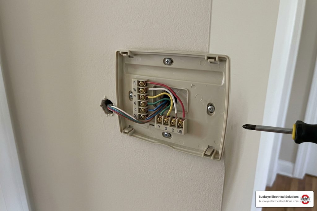
When you pop the faceplate off your current thermostat, you are greeted by a bundle of thin, colorful wires. In the vast majority of residential installations, these are 18-gauge solid copper wires bundled inside a protective plastic sheath. Because they carry a low-voltage 24-volt AC signal, they are physically much smaller than the 120-volt or 240-volt wiring that powers your outlets, lighting, or heavy appliances.
In the United States, there is a widely accepted industry standard for how these wire colors correspond to specific HVAC components. Knowing this standard makes upgrading your system much easier. You can review the complete color breakdown in this detailed guide to Thermostat Wire Color Codes For 3-8 Wire Thermostats (Color-By-Color).
However, you must remember one critical rule: never assume the previous installer followed the rules. While the colors usually match the standard terminals, we frequently find systems where a technician ran out of standard thermostat cable and used whatever colors they had on hand. Always verify the connections at both ends of the wire before making final terminations. You can learn more about these historical standards and structural types by reviewing the Thermostat Wires: Color Codes, Types And Guide For Americans.
Decoding the Standard Thermostat Wire Configuration
To help you make sense of what you see behind the wall, let’s break down the primary terminals and their standard color assignments.
- R Terminal (Red Wire): This is the hot wire that supplies 24-volt AC power from the transformer inside your furnace or air handler directly to the thermostat. Without this wire, your thermostat will not have power to trigger any other functions.
- W Terminal (White Wire): This wire controls your heating system. When the thermostat detects that your home has dropped below the set temperature, it closes the circuit between R and W, sending 24V power to your furnace or boiler to kick on the heat.
- Y Terminal (Yellow Wire): This wire manages your air conditioning. Closing the circuit between R and Y sends power to your outdoor condenser unit and compressor to start the cooling cycle.
- G Terminal (Green Wire): This wire controls your indoor blower fan. It allows you to run the fan continuously (in the “On” position) or automatically alongside heating and cooling cycles.
Below is a diagnostic table to help you identify common terminal failures, their likely causes, and how urgently they need to be addressed.
| Terminal Label | Standard Wire Color | Controlled HVAC Component | Likely Causes of Failure | Priority Level |
|---|---|---|---|---|
| R | Red | 24V Power Transformer | Blown low-voltage fuse, bad transformer, broken copper conductor | High |
| W | White | Heating System / Furnace | Faulty gas valve, failed ignition control board, loose terminal screw | High |
| Y | Yellow | Cooling Compressor | Tripped outdoor contactor, bad capacitor, broken thermostat wire | Medium |
| G | Green | Indoor Blower Fan | Failed fan relay, bad blower motor capacitor, loose G-terminal connection | Medium |
| C | Blue / Black | Common (Continuous Power) | Unconnected wire at furnace control board, broken common wire run | Medium |
Identifying Terminals When Colors Do Not Match
What happens if you open your thermostat and find a rainbow of non-standard colors, or wires that don’t match their terminals at all? This is where DIY projects can quickly go off the rails.
To solve this puzzle, you need to trace the physical cable back to your heating and cooling equipment. Open the access panel on your furnace or air handler and locate the main control board. There, you will find a matching terminal strip labeled with the exact same letters: R, W, Y, G, and C. By matching the physical color of the wire attached to the terminal on the furnace control board, you can confidently identify what that wire does at your wall plate.
If the wires are faded, dirty, or spliced inside the wall, a digital multimeter is your best friend. Setting your meter to test AC voltage allows you to measure the difference between the hot line (R) and the other conductors to verify which lines are active. For a deeper dive into safely working with residential electrical circuits, check out our Power Up Your Knowledge: A Beginner’s Guide to Home Wiring.
The Crucial Role of the C-Wire (Common Wire)
If you are upgrading to a modern smart thermostat, you will hear a lot of talk about the “C-wire” or “Common wire.” While older mechanical thermostats were simple switches that didn’t need their own power source to run, today’s smart models are essentially mini-computers. They feature high-resolution touchscreens, continuous Wi-Fi connections, and advanced sensors that require a constant, stable stream of electricity.
Why Smart Thermostats Require a C-Wire
To understand the C-wire, think of electricity as a flowing river. The Red (R) wire is the supply line that delivers 24-volt AC power from your furnace to the thermostat. But for electricity to do work, it must travel in a complete loop back to its source.
In older systems, the thermostat completed the loop through the heating (W) or cooling (Y) wires only when those systems were running. When the system was off, no power flowed. A smart thermostat, however, needs power 24/7.
Without a C-wire to complete the return path to the transformer, some smart thermostats attempt to “steal” power by running tiny amounts of current through the safety circuits of your furnace. This “power stealing” trick can cause your furnace to click on and off rapidly, damage your control board, or cause your smart thermostat to lose its Wi-Fi connection and reboot constantly. The C-wire provides a dedicated, continuous return path, ensuring total system stability.
Solutions for Systems Without a C-Wire
If your home was built before 2000, there is a strong chance you only have four wires running to your thermostat wall plate. Fortunately, you don’t necessarily have to tear open your drywall to run a new cable. There are several reliable workarounds:
- C-Wire Adapter / Power Extender Kit (PEK): Many smart thermostat manufacturers include or sell an adapter kit. These devices install inside your furnace cabinet, combining the signals of your existing G and Y wires so that one of them can be used to supply continuous power. For a step-by-step walkthrough on installing these adapters, refer to the How to Install a Smart Thermostat (DIY Guide) | Watt Wise.
- Using a Power Connector: Some brands offer brand-specific power accessories that connect directly to the furnace control board to provide power without requiring a dedicated common wire run. You can see how these adapters integrate into various system setups in the Thermostat E Installation Guide or the professional-grade Creative | GGL24405 | Nest Learning Thermostat (4th gen) Pro Install Guide (version 12/12/2024).
- Running a New Thermostat Cable: This is the most robust solution. If your basement is unfinished or access is clear, pulling a new 18/5 or 18/8 thermostat cable from the furnace to the thermostat wall plate gives you a clean, future-proof installation.
Single-Transformer vs. Dual-Transformer Systems
Most homes in Northeast Ohio rely on a single low-voltage transformer — usually located inside the furnace — to power both the heating and cooling systems. However, some homes feature completely separate heating and cooling setups, such as a boiler for winter heating and a separate high-velocity attic air conditioner for summer cooling. This is known as a dual-transformer system.
Wiring Rc and Rh Terminals
To accommodate these different configurations, thermostats feature two distinct power terminals: Rc (Red-Cooling) and Rh (Red-Heating).
- Single-Transformer Systems: When your home uses one transformer for both heating and cooling, a single red wire comes from the wall. In this setup, a small metal jumper wire or physical switch on the thermostat connects the Rc and Rh terminals together, sharing the single power source across both systems.
- Dual-Transformer Systems: If your heating and cooling systems are completely separate, you will have two distinct red power wires coming out of your wall — one from the furnace/boiler and one from the air handler. In this case, you must remove the jumper wire between Rc and Rh. Connect the heating power wire to Rh and the cooling power wire to Rc. Leaving the jumper in place will connect the two separate transformers together, which can burn out both control boards instantly.
If you are dealing with a complex boiler setup, you may find our specialized guides helpful, such as The Ultimate Drayton Cylinder Thermostat Wiring Guide or our detailed breakdown on Sparking Joy: The Ultimate Guide to Burnham Boiler Thermostat Wiring.
Heat Pump Systems and Reversing Valves
Heat pumps are increasingly common across Ohio because they offer highly efficient heating and cooling in a single unit. However, their wiring is slightly more complex than standard furnace and air conditioning setups.
The primary difference lies in how a heat pump changes direction. While a standard air conditioner only moves heat out of your home, a heat pump can reverse its refrigerant flow to pull heat into your home during the winter. It does this using a component called a reversing valve.
Heat Pump Thermostat Wire Configuration and Reversing Valves
To control the reversing valve, heat pump systems require an O/B terminal on the thermostat.
- The O/B Wire (Orange or Dark Blue): This wire tells the reversing valve whether to run in heating or cooling mode. Most manufacturers (like Carrier, Lennox, and Honeywell) energize the reversing valve on cooling, which uses the O setting (typically an orange wire). Other brands (most notably Rheem and Ruud) energize the valve on heating, using the B setting (typically a dark blue wire).
- Auxiliary and Emergency Heat (W2/AUX): Because heat pumps lose efficiency when outdoor temperatures drop below freezing, they rely on backup electric heat strips or a secondary gas furnace to keep your home warm on frigid Ohio winter nights. This auxiliary heat is controlled by the W2 or AUX terminal.
Configuring these settings incorrectly in your thermostat’s software can result in your system blowing freezing cold air when you call for heat, or hot air when you want cooling. For a complete walk-through of this specialized setup, read our guide Wire Up Your World: A Smart Thermostat Installation Walkthrough.
Step-by-Step Guide to Safely Replacing Your Thermostat
If you are ready to tackle a thermostat replacement, safety should always be your top priority. Follow this step-by-step process to ensure a smooth, hazard-free installation:
- Turn Off the Power: Go to your home’s main electrical panel and turn off the circuit breaker that powers your furnace and air conditioning systems. Never rely on simply turning the thermostat to “Off.”
- Verify Power is Off: Confirm the thermostat screen is blank and the system does not respond when you try to turn on the fan.
- Take a Picture: Pop the faceplate off your old thermostat and take a high-quality photo of the existing wiring. Make sure the terminal letters (R, W, Y, G, C) are clearly visible in the photo.
- Label Every Wire: Use the sticky labels included with your new thermostat to label each wire based on the terminal letter it is connected to — not the wire color.
- Disconnect and Secure: Carefully unscrew the wires and remove the old wall plate. Wrap the wires around a pencil or tape them to the wall so they don’t accidentally slip back inside the drywall cavity.
- Mount the New Backplate: Use a bubble level to ensure your new thermostat backplate is mounted straight, then secure it to the wall.
- Connect the Wires: Insert the labeled wires into their corresponding terminals on the new backplate. Ensure that about 1/4 inch of bare copper is exposed and securely clamped.
- Restore Power and Configure: Turn the circuit breaker back on and follow the on-screen prompts to configure your system type (conventional vs. heat pump).
As you perform updates around your home, keep in mind that local electrical standards keep pace with safety innovations. For example, Ohio’s 2023 NEC adoption includes expanded GFCI requirements in several locations, qualifying specific rules (like those in kitchens) as situational rather than universal. While low-voltage thermostat wiring does not fall under these specific GFCI rules, maintaining overall code compliance throughout your home’s electrical systems is vital. You can read more about standard local practices in The Essential Guide to Home Electrical Installation and consult general manufacturer guidelines in the Learning Thermostat Installation Guide.
Frequently Asked Questions About Thermostat Wiring
What should I do if my thermostat has no power?
Outlet has no voltage; could indicate breaker, GFCI, switch, or wiring issue. If your thermostat display is completely blank and won’t turn on, first check your main electrical panel to see if the furnace breaker has tripped. Next, check the service switch (which looks like a standard light switch) on or near your furnace cabinet to ensure it wasn’t accidentally flipped off.
Many modern furnaces also feature a small, purple 3-amp or amber 5-amp automotive-style fuse on the main control board. If you accidentally touched the Red (R) wire to the Common (C) wire while working on the thermostat with the power on, this fuse will blow to protect the transformer. Replacing this fuse is a simple, inexpensive fix, but if the transformer itself has failed, it will require professional replacement.
Can I use improper wiring or a bootleg ground to bypass a missing C-wire?
Absolutely not. Attempting to use a bootleg ground or connecting your common terminal to a nearby electrical ground rather than the dedicated furnace transformer common is an example of improper wiring that creates severe safety hazards.
Low-voltage standards exist to prevent electrical noise, protect sensitive microprocessor control boards, and avoid shock hazards. Bypassing these standards can destroy your HVAC equipment, void your manufacturer warranties, and even create a fire risk. If you do not have a C-wire, always use a manufacturer-approved power adapter kit or have a licensed electrician pull a new cable.
How do I know if my existing HVAC system is compatible with a new smart thermostat?
The vast majority of modern smart thermostats are designed for standard 24-volt low-voltage residential HVAC systems. However, they are not compatible with high-voltage line-voltage systems (which use thick 120V or 240V wires commonly found with electric baseboard heaters) or proprietary millivolt systems (often used in older gas fireplaces).
Most smart thermostat manufacturers offer a free online compatibility checker where you can input your existing wire labels to verify compatibility before making a purchase. You can also explore local options for smart system compatibility in this guide to WiFi Thermostats – Lew’s Reliable Heat & Air Conditioning.
Conclusion
Untangling a complex thermostat wire configuration can feel like trying to defuse a bomb in an action movie, but with a clear understanding of standard color codes, terminal functions, and safety protocols, you can approach the job with confidence.
However, if you find yourself staring at a messy web of spliced wires, dealing with a dual-transformer system, or feeling uncomfortable working around your home’s electrical systems, there is no shame in calling in the professionals. At Buckeye Electrical Solutions, we bring over 20 years of hands-on electrical experience directly to your doorstep. We serve homeowners throughout Northeast Ohio with prompt, friendly, and code-compliant services.
Any electrical estimate or service pricing we provide is subject to change depending on your local site conditions, system complexity, or local Authority Having Jurisdiction (AHJ) safety requirements. If you want to ensure your new smart thermostat is installed safely and configured perfectly, contact us today to schedule our top-rated residential electrical services.