What You Need to Know About the Drayton Cylinder Stat Wiring Diagram
Understanding the Drayton cylinder stat wiring diagram is essential before touching any wires on your hot water system. Here is a quick reference to address the most common wiring question — how the HTS3 terminals connect in a standard installation:
| HTS3 Terminal | Function | Typical Wire Colour |
|---|---|---|
| C (Common) | Incoming live from programmer | Brown |
| 1 (Call for Heat) | Switched live out to motorised valve | Brown |
| 2 (Satisfied) | Live when cylinder is up to temperature | Brown (if used) |
| No earth terminal needed | Double insulated — no earth required | – |
| Neutrals | Joined together, not connected to stat | Blue |
Key points at a glance:
- The HTS3 uses three terminals: Common (C), Call for Heat (1), and Satisfied (2)
- The circuit must be protected with a 3A fuse
- The thermostat is double insulated — no earth connection is needed at the stat itself
- If your motorised valve requires an earth, those wires should still be joined through separately
- Recommended temperature setting is 60°C
The Drayton HTS3 is a direct upgrade path from the older CS1 model, but the terminal labelling differs enough to cause confusion — and a wrong connection can leave you with no hot water or, worse, a safety hazard.
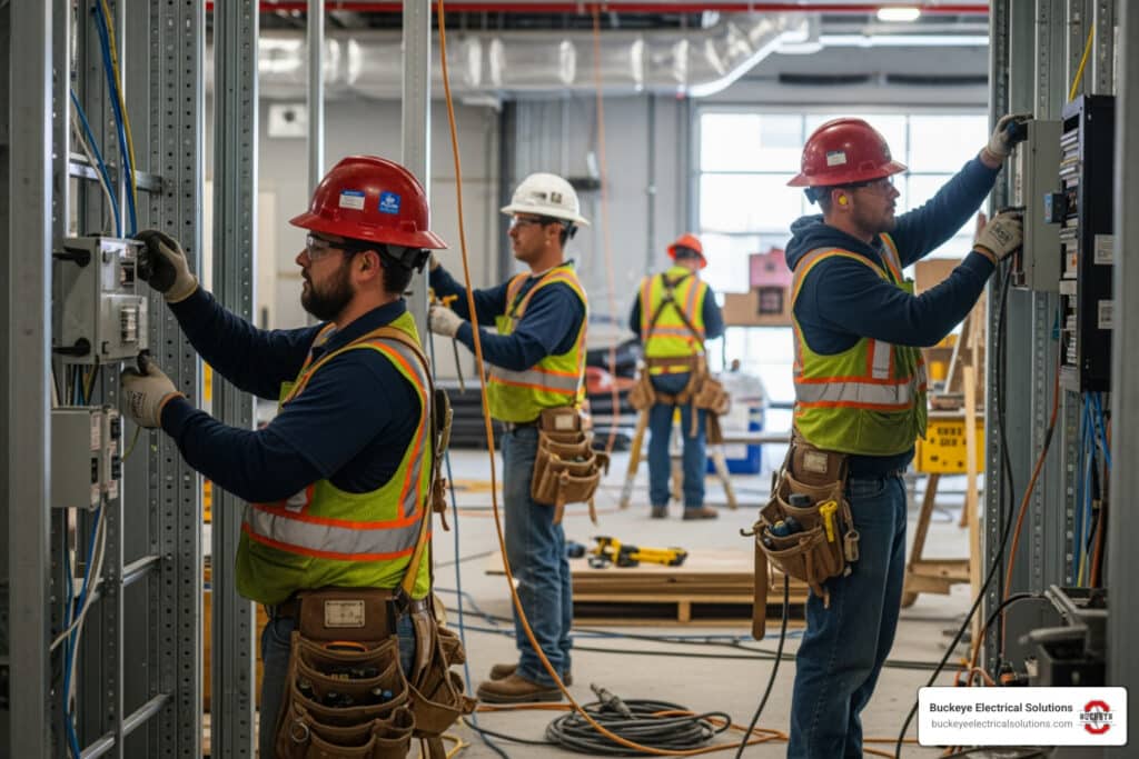
I’m Aaron, and through my work at Buckeye Electrical Solutions leading dozens of permitted electrical projects across Northeast Ohio, I’ve seen how a misread Drayton cylinder stat wiring diagram can turn a simple thermostat swap into an all-day troubleshooting job. In this guide, I’ll walk you through every step clearly so you get it right the first time.

Understanding the Drayton Cylinder Stat Wiring Diagram
A Drayton cylinder thermostat is a temperature-operated switch. It does not heat the water by itself. Instead, it senses the stored hot water temperature and switches heating controls on or off through the wiring center, programmer, boiler controls, and motorized valve.
In the Drayton HTS3, the switching arrangement is SPDT, meaning single pole, double throw. In plain English, one incoming live feed can switch between two outputs:
- C or Common: the incoming live feed, usually from the hot water channel of the programmer or wiring center
- 1 or Call for Heat: becomes live when the cylinder is below the set temperature and needs heat
- 2 or Satisfied: becomes live when the cylinder has reached the set temperature

The HTS3 technical ratings are important:
| HTS3 Specification | Detail |
|---|---|
| Temperature range | 50C to 80C |
| Differential | Approximately 8C |
| Switch type | SPDT |
| Switch rating | 3(1)A at 230V AC |
| Circuit protection | 3A fuse |
| Earth requirement | None at thermostat – double insulated |
| Typical setting | 60C |
| Energy class | Class I, 1% contribution under EU heating control classifications |
Even though the HTS3 is commonly discussed in 230V heating control systems, installations in Ohio must still be evaluated against the actual equipment, listing, manufacturer instructions, and the authority having jurisdiction. If the system is not a standard line-voltage control arrangement, do not guess. Guessing is how thermostats become tiny wall-mounted smoke machines.
The official Drayton HTS3 Installation & User Guide confirms the basic HTS3 terminal functions, mounting location, setting range, and double-insulated construction.
| Function | Older Drayton CS1 Concept | Drayton HTS3 Terminal | What It Usually Connects To |
|---|---|---|---|
| Common / live in | Common or live feed | C | Hot water ON feed from programmer or wiring center |
| Call for heat | Call / demand output | 1 | Motorized valve demand wire or wiring center hot water demand terminal |
| Satisfied | Satisfied / hot water off output | 2 | Used on some Y-plan or mid-position valve systems |
| Neutral | Not a thermostat switching terminal | Not connected to HTS3 switch | Joined separately if present |
| Earth / CPC | Earth continuity if required by connected equipment | No earth terminal required on HTS3 | Joined separately if valve or cable requires continuity |
The important rule is this: map by function, not by terminal number alone. Older controls may use different numbering, and some previous installations may not follow standard colors.
Step-by-Step: Replacing a Drayton CS1 with an HTS3

Before replacing a cylinder thermostat, we always start with safety. A cylinder stat may look like a small, simple device, but it can be part of a mains-voltage heating control circuit.
Basic process:
Turn off power to the heating controls
- Use the correct switch, fused spur, breaker, or service disconnect.
- Do not rely only on the programmer being set to OFF.
Verify the circuit is de-energized
- Use a suitable voltage tester or meter.
- Confirm your tester works before and after testing.
Photograph the existing CS1 wiring
- Take clear photos before loosening any terminal.
- Label wires if needed.
Identify cable groups
- One cable may come from the programmer or wiring center.
- Another may go to the motorized valve.
- In some systems, all connections are made at a central wiring box instead of inside the thermostat.
Remove the old CS1
- Loosen the retaining strap or spring cable.
- Disconnect wires only after labeling them.
- Avoid pulling on the cable.
Prepare the HTS3
- Remove the front cover.
- Check the terminal markings: C, 1, and 2.
- Route the cable so there is no strain on the terminals.
Reconnect by function
- Incoming live to C.
- Call for heat output to 1.
- Satisfied output to 2 only if the system uses it.
- Neutrals and earths handled separately, not landed on HTS3 switching terminals.
Refit and commission
- Secure the thermostat tightly to the cylinder.
- Restore power.
- Test hot water demand and satisfied operation.
If you are unsure whether a wire is live, neutral, switched live, or valve wiring, stop and test it properly. Wire color is a clue, not proof.
Mapping the Drayton Cylinder Stat Wiring Diagram for CS1 to HTS3
When replacing a Drayton CS1 with a Drayton HTS3, the safest way to think about the wiring is by control function.
The common replacement pattern is:
| Existing Function From CS1 Installation | Connects To On HTS3 | Notes |
|---|---|---|
| Live feed from programmer hot water ON | C | Usually brown in newer wiring |
| Switched live to motorized valve on hot water demand | 1 | Often another brown conductor |
| Hot water satisfied output, if used | 2 | Used in some mid-position valve arrangements |
| Neutral passing through thermostat location | Not to HTS3 | Join separately in an approved connector |
| Earth / CPC passing through thermostat location | Not to HTS3 | Join separately for continuity if required |
In a simple two-port valve hot water zone, the HTS3 usually works like this:
- Programmer calls for hot water.
- Live is sent to C on the HTS3.
- If the cylinder is cool, 1 becomes live.
- Terminal 1 sends power to the motorized valve.
- The valve opens, and its internal auxiliary switch may then signal the boiler and pump.
In a Y-plan or mid-position valve system, terminal 2 may matter more. The satisfied terminal can provide a “hot water off” signal to the valve control wiring. If you omit or misplace that wire in a system that needs it, the valve may not move correctly between hot water, heating, and mid-position.
For a standard Drayton cylinder stat wiring diagram, remember:
- C = feed in
- 1 = demand out
- 2 = satisfied out
- Blue is not automatically neutral if someone has used it as a control conductor
- Green/yellow should only be earth/CPC
The Drayton HTS3 Installation & User Guide is the primary reference for the HTS3 terminal layout. There is also a practical homeowner discussion on CS1-to-HTS3 replacement here: Replacing CS1 to HTS3 Forum Discussion. Forum examples can be useful, but they should never replace testing and the manufacturer instructions.
Handling Earth and Neutral Connections in the Drayton Cylinder Stat Wiring Diagram
The HTS3 is double insulated, so it does not need an earth connection at the thermostat body. That does not mean every earth wire in the box can be cut off or ignored.
Here is the correct approach:
| Wire Type | What To Do | Why |
|---|---|---|
| Earth / CPC to thermostat only | Park safely in an insulated connector if not required | HTS3 has no earth terminal |
| Earth continuing to motorized valve | Join through in an approved connector | The valve may require earth continuity |
| Neutral wires passing through | Join together separately if they are true neutrals | HTS3 switch does not use neutral |
| Blue used as switched live | Sleeve or mark correctly | Prevents dangerous misidentification |
| Unused conductor | Cap safely in an approved connector | Prevents accidental contact |
In many cylinder stat replacements, especially where the stat sits between a programmer and a motorized valve, you may see:
- Brown from supply/programmer
- Brown to valve
- Blue neutrals joined
- Green/yellow earths joined
That can be correct in some installations, but never assume. Older heating systems often contain wiring that has been modified over time. We have opened heating controls where wire colors told one story and the meter told a completely different one. The meter wins.
If the connected motorized valve requires an earth, maintain that earth connection. The HTS3 does not need an earth for itself, but downstream equipment may still rely on the CPC.
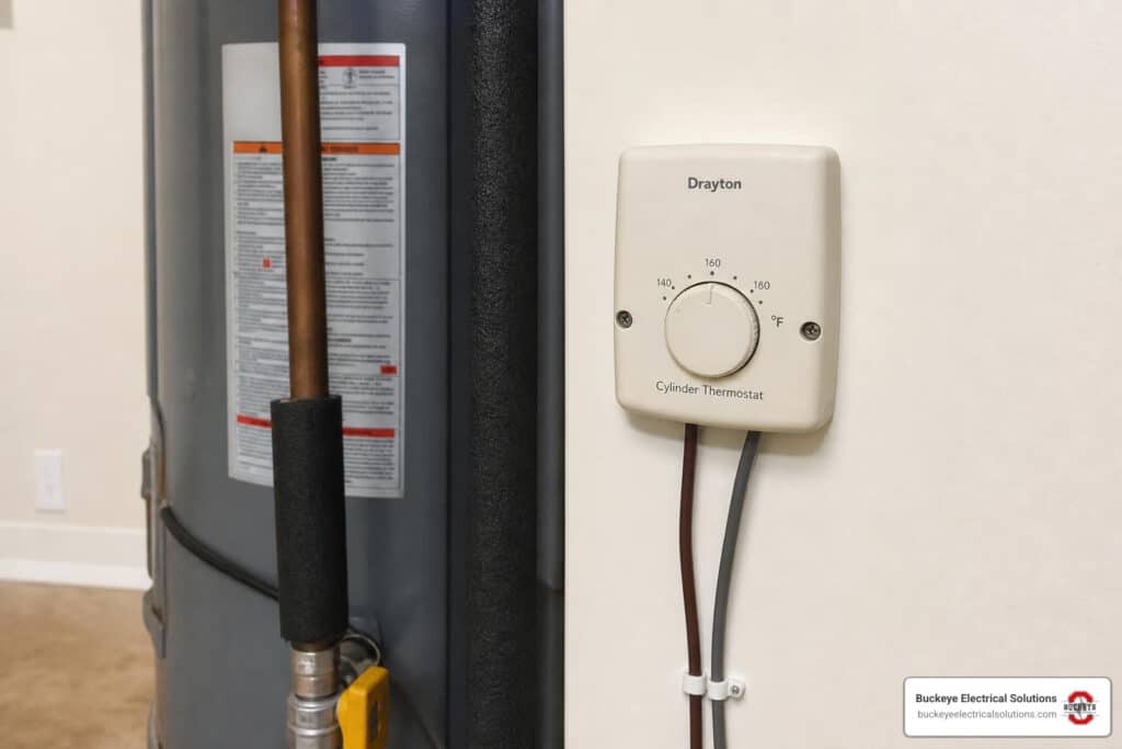
Physical Installation and Positioning on the Hot Water Cylinder
Electrical wiring is only half the job. A cylinder thermostat also has to sense temperature accurately. If it is loose, mounted too low, buried in insulation, or barely touching the cylinder, it can behave badly even when wired correctly.
The HTS3 should be installed:
- About one third of the way up the hot water cylinder
- On the front of the cylinder for access
- In firm contact with the metal surface
- Away from pipe fittings or areas affected by unusual heat transfer
- With the fixing cable or strap tight enough to hold the stat flat
For pre-insulated cylinders, a small area of insulation may need to be removed so the thermostat base contacts the cylinder metal. Remove only what is necessary. The goal is good contact, not giving the tank a haircut.
Drayton guidance states that the spring fixing cable should be cut to an unstretched length around 2.5 to 3 inches less than the cylinder circumference. This helps maintain enough tension to keep the thermostat pressed against the cylinder.
Good installation checklist:
| Installation Detail | Correct Practice |
|---|---|
| Height | Around one third up the cylinder |
| Location | Front-facing for service access |
| Contact | Flat against bare cylinder metal |
| Cable strain | No tension on terminals |
| Fixing method | Spring cable or approved strap secured firmly |
| Insulation | Remove only enough to allow sensing contact |
Poor physical contact can cause symptoms that look like wiring faults:
- Water gets hotter than the thermostat setting
- Boiler keeps cycling
- Hot water temperature swings widely
- Thermostat seems slow to respond
- Tap temperature is much higher than expected
This happens because water inside a cylinder naturally stratifies. Hotter water rises to the top, cooler water stays lower. A thermostat senses only the temperature where it touches the cylinder wall. If it is loose by even a small gap, it may read cooler than the stored water really is.
Commissioning and Setting the HTS3 Thermostat
Once the HTS3 is wired and mounted, it needs to be commissioned. Commissioning simply means checking that the system responds correctly before walking away.
The HTS3 setting range is 50C to 80C, with a differential of roughly 8C. A common hot water setting is 60C. Many systems are set between 60C and 65C to balance comfort, hygiene, and energy use.
Why 60C is popular:
- Hot enough to help control bacteria risk in stored water systems
- Not excessively high for normal domestic hot water
- Helps reduce wasted energy
- Helps limit scalding risk compared with higher settings
Important: turning the cylinder thermostat higher does not make the water heat faster. The heat-up rate depends on the boiler output, coil size, water volume, flow temperature, and system design. The thermostat setting only tells the system when to stop.
Commissioning steps:
Set the programmer to call for hot water
- Make sure heating controls are active.
Turn the HTS3 setting high
- Rotate the setting arrow fully clockwise for maximum demand during testing.
- The motorized valve should open if the water is cooler than the setting.
Check for call for heat
- Terminal 1 should energize when the stat calls.
- The boiler and pump should respond through the valve and wiring center arrangement.
Turn the HTS3 down
- Rotate anticlockwise toward OFF or below cylinder temperature.
- The call should stop.
- If terminal 2 is used, it should become active when satisfied.
Set final temperature
- Set the arrow to the desired stored water temperature.
- 60C is a common final setting.
Check boiler flow temperature
- The boiler or system flow temperature must be high enough to heat the cylinder to the thermostat setpoint.
- If the cylinder stat is set higher than the boiler can deliver, the system may run continuously.
Refit covers
- Replace all covers and verify strain relief.
- Make sure no copper conductor is exposed outside terminals.
Troubleshooting Common Cylinder Stat Wiring Issues
Cylinder stat problems usually fall into two categories: wiring faults and sensing faults. The tricky part is that both can create similar symptoms.
Before troubleshooting, isolate safely and test properly. In Ohio, electrical work must comply with applicable codes, product instructions, and local AHJ requirements. Ohio’s 2023 NEC adoption includes expanded GFCI requirements in several locations, but specific rules – including kitchen, utility, basement, garage, and equipment-location requirements – are situational rather than universal. The exact requirement depends on the circuit, location, equipment, and local enforcement.
For general electrical diagnosis, remember this exact condition: Outlet has no voltage; could indicate breaker, GFCI, switch, or wiring issue. While that phrase is not specific to cylinder stats, the same principle applies to controls: no voltage at one point does not automatically identify the failed part. You have to trace the circuit.
| Symptom | Likely Causes | Priority Level |
|---|---|---|
| No hot water demand | No live feed to C, programmer off, blown 3A fuse, failed stat, wiring center issue | High |
| Valve does not open | Terminal 1 not energized, valve motor fault, neutral missing, improper wiring | High |
| Boiler runs continuously | Call and satisfied wires crossed, stat set too high, valve end switch issue, poor stat contact | High |
| Water much hotter than setting | Poor cylinder contact, stat mounted too low, thermal stratification, failed thermostat | Medium to High |
| Heating works but hot water does not | Programmer hot water channel fault, cylinder stat wiring error, motorized valve issue | High |
| Hot water works only on manual valve lever | Valve motor or control feed issue, missing switched live, wiring center problem | High |
| Fuse blows after replacement | Short circuit, neutral/live mix-up, damaged cable, incorrect terminal connection | Urgent |
| HTS3 has no earth terminal | Normal – double insulated design | Low if earth continuity is otherwise maintained |
| Blue wires at stat location cause confusion | True neutrals may be joined, but blue may also be repurposed as switched live | Medium |
Common wiring mistakes when upgrading from CS1 to HTS3 include:
- Mapping by terminal number instead of function
- Putting neutral onto a thermostat switch terminal
- Leaving the motorized valve earth disconnected
- Connecting both call and satisfied incorrectly
- Assuming every brown wire is the same feed
- Failing to sleeve a blue switched live
- Not checking the 3A fuse
- Mounting the thermostat loosely after wiring
- Forgetting that some mid-position systems require terminal 2
Compatibility issues are usually not because the HTS3 cannot replace the CS1. More often, the problem is that the old wiring was non-standard, undocumented, or part of a more complex valve arrangement. A two-port valve system and a mid-position valve system can use the cylinder stat differently.
A good troubleshooting order is:
- Confirm safe isolation and inspect wiring.
- Confirm the 3A fuse is intact.
- Confirm programmer hot water output reaches HTS3 C.
- Confirm terminal 1 energizes on call for heat.
- Confirm terminal 2 operation if the system uses satisfied output.
- Confirm valve neutral and earth continuity.
- Confirm the valve opens and its auxiliary switch operates.
- Confirm the boiler and pump receive demand.
- Check physical thermostat contact and cylinder position.
- Set final temperature and observe a full cycle.
If the system has been modified several times, it may be faster and safer to have a qualified electrician or heating controls technician trace it properly. We like solving puzzles, but we prefer puzzles that do not involve live terminals and mystery cables.
Frequently Asked Questions about Drayton Cylinder Thermostats
Where should the Drayton HTS3 be positioned on the cylinder?
The Drayton HTS3 should be positioned approximately one third of the way up the hot water cylinder, usually on the front for easy access. It must sit firmly against the metal surface of the cylinder.
If the cylinder is foam-insulated, remove only enough insulation to allow direct metal-to-thermostat contact. If the thermostat is loose or mounted over insulation, it may read incorrectly and allow the water to overheat.
Does the Drayton HTS3 require an earth connection?
No. The HTS3 is double insulated and does not require an earth connection at the thermostat itself.
However, earth wires should not simply be cut away. If earth conductors pass through the thermostat location, or if the motorized valve requires earthing, those earths should be joined through using an approved connector to maintain continuity.
Why is my hot water much hotter than the thermostat setting?
The most likely causes are poor thermostat contact, incorrect position on the cylinder, thermal stratification, or a wiring fault.
Hot water cylinders naturally have hotter water near the top and cooler water lower down. Since the thermostat only senses the temperature at its mounting point, poor contact or low mounting can make the thermostat think the water is cooler than it really is. The result is water at the taps that is much hotter than the dial setting.
Also check:
- The thermostat is tight against bare metal
- It is about one third up the cylinder
- The boiler flow temperature is not excessive
- Terminal 1 and terminal 2 are not crossed
- The motorized valve closes correctly when satisfied
Conclusion
A correct Drayton cylinder stat wiring diagram comes down to three things: identify the terminals by function, maintain safe neutral and earth continuity, and mount the thermostat properly on the cylinder.
For the HTS3:
- C receives the incoming live from the programmer or wiring center
- 1 sends the call for heat to the motorized valve or hot water demand circuit
- 2 provides the satisfied output where the system requires it
- The thermostat itself needs no earth
- Neutrals are joined separately if present
- The circuit should be protected by a 3A fuse
- The stat should be mounted about one third up the cylinder
- A final setting around 60C is common
At Buckeye Electrical Solutions, we help Ohio homeowners and businesses with safe electrical repair, installation, maintenance, heating control wiring, and thermostat upgrades. With over 20 years of experience, we focus on clean workmanship, code-conscious installation, and getting the job done promptly.
For related thermostat guidance, see our smart thermostat installation walkthrough.